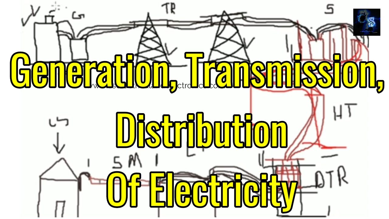
Hello Guys, welcome back to my blog. In this article, I will discuss generation, transmission, and distribution of electricity, how the electricity is transferred from generating stations to consumers.
If you want an article on some other topics then comment us below in the comment box. You can also catch me @ Instagram – Chetan Shidling
Also read – Electrical Machines Questions And Answers.
Generation Transmission And Distribution Of Electricity
The journey of electricity will starts from the power plant and ends at the consumer. From power plant to the consumer in between there are many stages, they are :
- 01. Power Plant
- 02. The station at Power Plant
- 03. Transmission Lines
- 04. Sub-station
- 05. High Tension(HT) Lines
- 06. Distribution Transformer Station
- 07. Low Tension(LT) Lines
- 08. Service Mains
- 09. Consumer
Now I will discuss step by step what is a power plant, step-up station, transmission lines, sub-station, high tension lines, distribution transformer station, low tension lines, service mains, and utilized. Now I will discuss in a deep the generation, transmission, and distribution of electricity.
01. Power Plant

Power plant means where the electricity is generated. examples of the power plant are hydropower plant, thermal power plant, nuclear power plant, and solar power plant these are the power plants which generate electricity. The voltage generated in power plants is normally of 11KV, this voltage is very low which cannot be transmitted to a long-distance, if the 11KV voltage is transmitted to a long distance then there will be losses in the transmission line. So to avoid loss in the transmission line, the step-up station is located in a power plant.
02. Step-up Station

The power plant also consists of the step-up station where the 11 KV voltage is stepped-up to 110 KV, 220 KV, etc then this high voltage can be transmitted for a long distance without any losses.
Why the voltage is stepped-up?
The voltage produced in the power plant is very low and current is more, if we transmit that voltage for a long-distance than losses will occur in the transmission line, to avoid losses in transmission line voltage is stepped-up and current will become low, if low current and high voltage is transmitted through transmission line the efficiency of the line will be good.
03. Transmission Lines
Transmission lines are nothing but a conductor used to transmit electricity from power plants to sub-station. Transmission lines are erected outside the city because of high voltage. Transmission lines are classified into two types: single-circuit transmission line and double circuit transmission line. The single circuit transmission line carries only three conductors whereas the double circuit transmission line carries six conductors as shown in the below figure.
04. Sub-station

Sub-station means which consists of the number of equipment that is used to step-down the voltage, controlling, and switching. The voltage from transmission line i.e., 110 KV or 220 KV is step-down to 11 KV. The equipment used in the sub-stations is lightning arrestors, circuit breakers, isolators, step-up transformer, insulators, reactors, capacitors bank, and control room. Apart from this generation, transmission and distribution of electricity, I will also discuss substation.
Sub-stations and its Equipment
Sub-stations are used throughout the electrical power system. Starting with the generating station, a sub-station raises the medium-voltage generated by the alternators to the high-voltage needed to transmit the electrical energy economically. The high transmission line voltage is again reduced in other sub-stations i.e., distribution transformer station located near to the consumers.
The Sub-station consists of the following main units :
- (01). Bus-bars
- (02). Insulators
- (03). Isolators
- (04). Circuit breaker
- (05). Current Transformer ( CT )
- (06). Potential Transformer ( PT )
- (07). Indicating instruments
- (08). Earthing
- (09). Battery room
- (10). Control room
(01). Bus-bars :
In the station a number of lines operating at the same voltage have to be connected electrically, bus bars are used for this purpose to connect many conductors. Bus bars are made of high conductivity conducting material, copper, or aluminum. Copper is used for high current indoor materials and switchgear bus bars where space is restricted. Tubular aluminum pipes and flexible ACSR conductors are used for outdoor bus bars.
(02). Insulators :
Insulators are used in generating stations and sub-stations to fix and insulate the bus-bar systems.
Insulators used in stations are mainly Disc Insulators.
(03). Isolators ( Disconnectors ) :
Insulators give physical separation between the live part and the dead part, these are triple pole units with manual or motor mechanisms. During the opening, the blades swing in horizontal ( or vertical ) position and contacts are separated. During the closing, contacts come together. Isolators are not designed to close or open with the current. Hence isolators can be opened only after opening the CB. Similarly, isolators can be closed only after closing the CB.
(04). Circuit breaker :
A circuit breaker is a protective device or equipment which is used to protect the circuit from overload and short circuit condition. A circuit breaker can be operated during load conditions and also during the no-load condition. Circuit breaker breaks or interrupts the circuit in a fault condition.
(05). Current Transformer :
A Current Transformer is a step-up transformer that is used to step down the current to know ratio i.e., CT has used for step downing the ac current from normal value to low value for the protection and also for measurement.
(06). Potential Transformer :
It is a step-down transformer and which step-downs the voltage to a known ratio. The voltage is stepped down for measurement and also for protection. Typical ratios are 110 KV/100 V volt-ampere ratings are low e.g., 100 VA, 150 VA.
(07). Indicating instruments
(08). Earthing
(09). Battery room
(10). Control room
05. High Tension Lines

HT lines carry electricity from substations to the distribution transformer station. The HT line carries 11 KV voltage. Tapping can be taken from HT lines. HT lines are erected only on the main roads of cities. The HT line carries three conductors (R Y B). The conductor used in a high tension line is of ACSR type (aluminum conductor steel reinforced ).
06. Distribution Transformer Station
The main purpose of the distribution transformer is to step-down the voltage from 11 KV to 440 volts (three phases) and 230 volts (single-phase). DT station are again classified into two types: single pole-mounted station and double pole-mounted station
Here I will discuss the double pole distribution transformer station.
The materials used in the DP structure are :
a. Lightning Arresters
11 KV class lightning arrestors are used and lightning arrestors are fixed at the top of the DP structure as you can see in the above image. The function of the lightning arrestor is to protect the transformer from lightning tenders. When the lightning occurs and falls on structure the lightning arrestor transfers lightning stocks to the ground and thus protects the transformer. A total of three lightning arrestors is provided.
b. Fuse
It is called horn gap fuse for the protection of the transformer from overload and short circuit current. When overhead occurs on the ht line (11KV line), the fuse will isolate the circuit and thus protect the transformer.
c. GOS
As you can see in the above image, it is called GOS or Gange operating switch. The purpose of the gange operating switch is to isolate the circuit during repair conditions, By using the gange operating switch at a time all the lines can be disconnected.
d. Distribution Transformer
The main purpose of the transformer is to step down the voltage from 11 KV to 440 volts ( three phases) or 230 volts (single-phase).
e. LT Metering Box
LT metering box consists of some relays, meter, etc. LT metering box will be placed at the bottom of the structure.
f. Earthing System
A total three no of earthing will be provided for DP structure, one earth will be connected to the lightning arrester, another earthing will be connected to the transformer neutral, and third, earthing will be connected to all the parts of the DP structure.
All the earthing is also interconnected to each other.
07. Low Tension Lines
The main purpose of the LT line is to transmit electricity to every consumer. low tension lines are erected in every street of cities. The low tension line carries four conductors i.e., three conductors for phase and one conductor for neutral. ACSR conductors are used in LT lines.
08. Service Mains

The main purpose of the service main is to connect the LT line to the consumer meter board. Service mains are gain classified as overhead service mains and underground service mains.
The overhead line or U.G cable connecting the supplier’s distribution line to the consumer’s premises is called service mains or service connection or service line.
09. Consumer
The consumer who utilize the electricity for there purpose. Electricity is utilized through loads like a fan, washing machine, TV, lights, etc.
So, guys, I hope this article may help you all a lot.
Thank You For Reading.
Tag: Generation Transmission And Distribution Of Electricity.
Also, read:
- 10 Tips To Maintain Battery For Long Life, Battery Maintainance
- 10 Tips To Save Electricity Bills, Save Money By Saving Electricity
- 100 (AI) Artificial Intelligence Applications In The Automotive Industry
- 100 + Electrical Engineering Projects For Students, Engineers
- 100+ Indian Startups & What They Are Building
- 1000+ Automotive Interview Questions With Answers
- 1000+ MATLAB Simulink Projects For MTech, Engineering Students
- 2024 Is About To End, Let’s Recall Electric Vehicles Launched In 2024
- 2026 Hackathons That Can Change Your Tech Career Forever
- 50 Tips To Save Electricity At Home, Shop, Industry, Office
- 50+ Question And Answer On The Substation, Electrical Question
- 500+ Matlab Simulink Projects Ideas For Engineers, MTech, Diploma
- 7 Ways EV Batteries Stay Safe From Thermal Runaway
- 8 Reasons Why EVs Can’t Fully Replace ICE Vehicles in India
- Active Cell Balancing Using A Flyback Converter Simulation In Matlab Simulink
- AI Artificial Intelligence Applications In Electric Vehicles | Future?
- AI Tools For Electronic Circuit Design, Which Is Best?
- All-Wheel Drive (AWD) Vs Front-Wheel Drive (FWD) Vs Rear-Wheel Drive (RWD): Which Is Better?
- Applications Of Artificial Intelligence (AI) In Renewable Energy
- Artificial Intelligence-Based Electrical Machines & Drives