
Hello guys, welcome back to my blog. In this article, I will discuss active cell balancing using a flyback converter simulation in Matlab Simulink, I will show simulation, waveforms, Matlab function block code, etc.
If you have any electrical, electronics, and computer science doubts, then ask questions. You can also catch me on Instagram – CS Electrical & Electronics And Chetan Shidling.
Also, read:
- Top 10 Lithium-ion Battery Manufacturing Companies In The World
- 10 Tips To Maintain Battery For Long Life, Battery Maintainance
- lithium-ion battery Working, Advantages, Disadvantages, Materials Used
Active Cell Balancing Using A Flyback Converter Simulation In Matlab Simulink
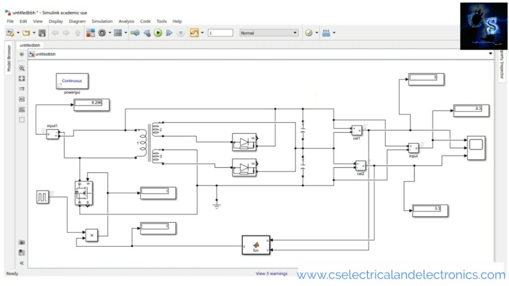
The above circuit shows active cell balancing using a flyback transformer. In this technic, I am using capacitors instead of cells and I will make the voltage of each capacitor equal by applying the cell balancing technic. I gave the initial voltage of capacitors as 3 and 3.3 as you can see in the above image.
The initial voltage of capacitor 01 is 3 and the initial voltage of capacitor 02 is 3.3, when the cell balancing has applied the voltage across each capacitor will be average of two capacitors, i.e, 3.15 volts.
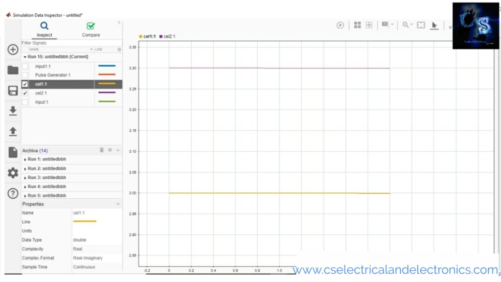
As you can see in the above image. The waveform of capacitors voltage. The initial voltage of capacitor 01 and capacitor 02 is 3 and 3.3.
The active cell balancing circuit consists of;
01. Linear transformer
The input to the linear transformer will be the sum of two capacitor voltage. It is a 1:2 ratio transformer. The secondary side has two winding, each winding gets equal voltage i.e., the average of capacitor voltage.
02. Diodes
In this circuit, the diode conducts only if the anode voltage is greater than the cathode voltage. If the anode voltage is not greater than the cathode voltage than the diode does not conduct.
03. Product
The purpose of the product is to produce a switching pulse to Mosfet when both capacitor voltages are not equal. When the voltage of both capacitors becomes equal than the product gives a low output(0) and hence Mosfet will be turn off and the circuit will be opened.
04. Mosfet
It is used as a switch to make the circuit close or open.
05. Matlab function
In Matlab Function, I wrote the code which will compare the voltage of both capacitors.
06. Current measurement
The current measurement is used to measure the current flowing in the circuit.
07. Voltage measurement
The voltage measurement is used to measure the voltage across the two capacitors, capacitor 01 and capacitor 02.
08. Scope
It is used to display the waveforms of voltage and current.
09. Display
It will display the value of voltage and current as you can see in the above images.
10. Capacitor
Instead of a cell, I am using a capacitor for balancing.
11. Pulse generator
It will produce a pulse to the gate of the Mosfet.
- Amplitude = 1
- Period = 10
- Pulse width = 50
- Phase delay = 0
Working Of Circuit Diagram
The circuit working is simple, initially, the voltage of capacitor 01 is 3, and the voltage of capacitor 02 is 3.3, to make both capacitor voltage the same we are using active cell balancing. The voltage across the two capacitors is 6.3 which is fed to the linear transformer as input. The secondary side has two windings, both carry equal voltage. When the anode voltage is greater than the cathode then the diode conducts and charges the capacitor. When the anode voltage is less than the cathode then the diode does not conduct and the capacitor only discharges.
The Matlab function will compare the voltage of each capacitor. When the voltage across each capacitor becomes equal the Mosfet turn off and hence circuit will become open.
Now, I will share the circuit diagram and waveform after applying cell balancing.

Now, you can see the voltage on display. The voltage across each capacitor is equal. Inactive cell balancing, the energy of one capacitor is transferred to another capacitor. The 1.5 volts of capacitor 02 is transferred to capacitor 01.
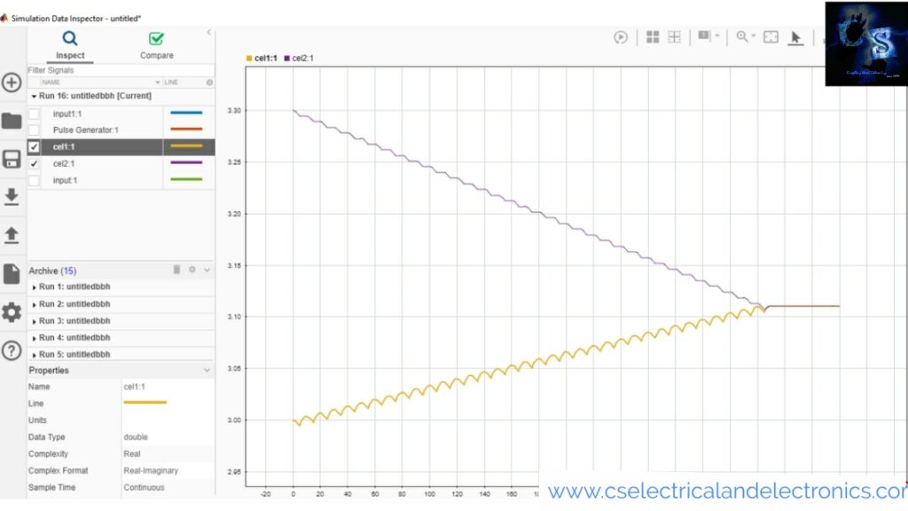
The above images show the waveform of active cell balancing. As you can see the voltage becoming equal.
I hope this article may help you all a lot. Thank you for reading.
Download file – Click Here
Also, read:
- How Digital Twins Are Revolutionizing the Automotive Industry
- The Future of AI Data Centers: Underwater, Underground, Nuclear & Space!
- Fast Charging vs Slow Charging: Which One Is Better for Your EV Battery?
- Highest-Paying Career Fields for EEE & ECE Engineers in 2026
- Embedded Engineer To AI Engineer Roadmap
- India’s First Private Orbital Rocket: How Skyroot Aerospace’s Vikram-1 Is Transforming the Future of India’s Space Industry
- Visually Explained MAAB / MAB Modeling Guidelines
- Visually Explained MISRA Guidelines
Tag: Active Cell Balancing Using A Flyback Converter Simulation In Matlab Simulink


Excellent professional service is done by you. Many thanks for your service again.
Hello. This simulation is working. But i want to use ten cell and i want to replace the capacitor with lithium ion battery. Can you help me ?
Good work sir.This circuit is simply good for balancing.I want to replace the capacitor with battery.Could you help me sir?
Hey ! Can you please contact me.. I have a proposal for … I want to learn how you calculated the parameters. I am ready to pay for that
good job,
Can you please share the simulation file with me.
Thanks
Here is the link https://www.cselectricalandelectronics.com/product/active-cell-balancing-in-lithium-ion-battery-for-battery-management/
Could you send the paper youve referred to ?