Hello guys, welcome back to my blog. In this article, I will discuss the difference between unity, lagging, and leading power factor, what is the unity power factor, what is lagging power factor, what is leading power factor, etc.
If you require an article on some other topics then comment us below in the comment box. You can also catch me @ Instagram – Chetan Shidling.
Also, read:
- Difference Between SCR, DIAC, TRIAC |Definition, Construction
- Difference Between Microprocessors And Microcontrollers
- Difference Between Machine Learning Artificial Intelligence Deep Learning
- Difference Between Arduino Uno, Nano, Mega, Features, Applications
Difference Between Unity, Lagging, Leading Power Factor
What is power factor?
The power factor is the cosine of the angle between voltage and current in AC circuits. Or it can be also defined as the ratio of true power to the total power or apparent power.
Power factor = true power / total power
True power – The power which will be utilized to do some useful work is called true power. This will be the fraction of the total power that is being supplied to the particular device.
Reactive power – The power which will be used to exchange electrical and magnetic fields in the circuit is called reactive power.
Apparent power – The vector sum of true power and the reactive power is called apparent power.
Note: We get the power factor only in AC circuits but not in DC circuits as frequency zero there is no power factor.
Let’s understand about power factor cases by taking circuit diagrams.
Unity Power Factor
Consider a purely resistive load that will be connected to the voltage source. We know that in the pure resistive load the voltage and current are in phase with each other. This can be seen in the below waveform.

In the above waveform both voltage and current changes simultaneously that’s why the angle between voltage and current will be O. As we know the power factor is the cosine of the angle between voltage and current, therefore, Cos0=1 in the pure resistor circuit, the power factor will be unity.
Leading Power Factor
The leading power factor can be achieved by using the capacity load in the circuit. Because the pure capacity load current leads the voltage by angle 90°. We can also get leading power factors in the combination with resistive capacitive loads in the circuit.

Consider the wave forms as I shown below,
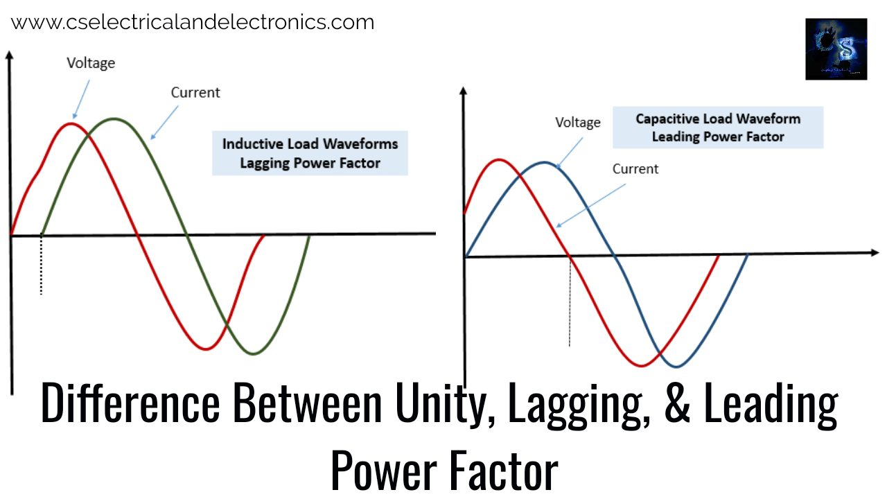
In the above waveform, the current and voltage are changing at different times. So there will be some angle in between voltage and current, this angle is nothing but power factor angle. As I mentioned above in the case of capacitive load the current leads the voltage by 90°. So we can get leading power factors in the case of a purely capacitive circuit. In the waveform, the current I encounters the zero crossings of the axis a little bit earlier than that of voltage. This is referred to us the leading power factor. The leading power factor will improve voltage regulation, and it causes less power consumption by the load.
Lagging Power Factor
Consider this circuit with a purely inductive load. We know that in the purely inductive circuit current lags with the voltage by angle 90°. That’s why the power factor in the inductive load will be lagging in nature. Let’s look at the waveform as I have shown below,

In the above waveform, both current and voltage are changing at different times. The current starts to flow after voltage. So there will be some angle in between current and voltage. The circuit with a lagging power factor consumes more power.
Difference Between Unity, Lagging, Leading Power Factor
01. The leading power factor can be attained when the current leads voltage that is in the pure capacity circuit. The lagging power factor can be attained when the current lags the voltage in the purely inductive circuit we can get lagging power factor. Unity power factor can get when voltage and current are in phase with each other.
02. In the leading power factor circuit, the phase angle of current is positive with respect to voltage, whereas in lagging power factor circuit the phase angle of current is negative with respect to voltage.
03. The leading power factor can be corrected by the addition of inductive loads, whereas the lagging power factor can be corrected by the addition of capacitive loads.
04. In the case of leading power factor reactive component will be negative, whereas in the case of lagging power factor the reactive component will be positive. Unity power factor circuit doesn’t use any reactive power, it’s considered as a perfect power factor.
05. The leading power factor varies from -1 to 0, whereas the lagging power factor varies from 0 to 1. In the unity power factor circuit, the power will be always 1, as the name suggests.
06. Examples for the leading power factor are radio circuits, electric motors power supplies, etc. Examples for the lagging power factor are repulsion induction Motors, power generators, relays.
I hope this article may help you all a lot. Thank you for reading. If you have any doubts related to this article, then comment below.
Also, read:
- 10 Tips To Maintain Battery For Long Life, Battery Maintainance
- 10 Tips To Save Electricity Bills, Save Money By Saving Electricity
- 100 (AI) Artificial Intelligence Applications In The Automotive Industry
- 100 + Electrical Engineering Projects For Students, Engineers
- 100+ Indian Startups & What They Are Building
- 1000+ Automotive Interview Questions With Answers
- 1000+ MATLAB Simulink Projects For MTech, Engineering Students
- 2024 Is About To End, Let’s Recall Electric Vehicles Launched In 2024
- 2026 Hackathons That Can Change Your Tech Career Forever
- 50 Tips To Save Electricity At Home, Shop, Industry, Office
- 50+ Question And Answer On The Substation, Electrical Question
- 500+ Matlab Simulink Projects Ideas For Engineers, MTech, Diploma
- 7 Ways EV Batteries Stay Safe From Thermal Runaway
- 8 Reasons Why EVs Can’t Fully Replace ICE Vehicles in India
- Active Cell Balancing Using A Flyback Converter Simulation In Matlab Simulink
- AI Artificial Intelligence Applications In Electric Vehicles | Future?
- AI Tools For Electronic Circuit Design, Which Is Best?
- All-Wheel Drive (AWD) Vs Front-Wheel Drive (FWD) Vs Rear-Wheel Drive (RWD): Which Is Better?
- Applications Of Artificial Intelligence (AI) In Renewable Energy
- Artificial Intelligence-Based Electrical Machines & Drives