Hello guys, welcome back to my blog. In this article, I will discuss the current transformer and potential transformer, circuit diagram of the current transformer and potential transformer, why the secondary side of the current transformer should not be open, etc.
If you require an article on some other topics then comment us below in the comment box. You can also catch me @ Instagram – Chetan Shidling.
Also, read:
- Difference Between LT, HT, And Transmission Lines, Conductors Used.
- Difference Between Unity, Lagging, Leading Power Factor, Definition.
- Switched Reluctance Motor (SRM), Construction, Working, Drive System.
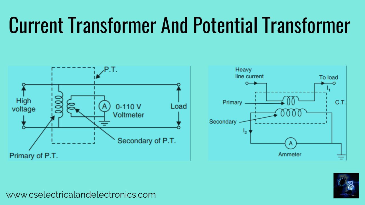
Current Transformer And Potential Transformer
Instrument transformers are meant to transform voltage or current of the high values in the transmission and distribution systems to the low values that can be used by low voltage metering devices. Instrument transformer also isolates protection, measurement, and control circuitry from the high currents or voltages present on the circuits being measured or examined. There are two types of instrument transformers, both are given below:
- Current Transformer
- Potential Transformer
The current transformer (CT) together with potential transformer (PT), is recognized as instrument transformers.
Current Transformer

The current transformer (CT) is utilized for the analysis of electric currents. While the current in a circuit is likewise high to directly connect to measuring instruments, a current transformer provides a reduced current exactly proportional to the current in the circuit, which can be conveniently connected to recording and measuring instruments. It used in association with current measuring devices, its primary winding is meant to be connected in series with the line.
It is important that the impedance of the primary winding be made as small as possible. The secondary winding turns is more than the primary winding. The ratio of primary to the secondary current is inversely proportionate to the ratio of primary to secondary turns. This transformer is normally a step-up transformer in terms of primary to secondary turn ratio.
In the current transformer, the load impedance or burden on the secondary is very less, so the current transformer works on short-circuit conditions. The current into the secondary winding depends upon the current flowing in the primary winding. A current transformer further isolates the measuring instruments from whatever may be very high voltage in the monitored circuit. A current transformer is generally used in metering and protective relays in the electrical power industry.
As marked from the picture the primary winding of the transformer is connected in series with the line carrying high current. The secondary of the transformer is built up of a large number of turns of fine wire owning a small cross-section area. This is connected to the coil of the normal range ammeter.
The transformer is primarily a step-up transformer, it’s step-up a voltage from primary to secondary. So it reduces the current from primary to secondary. From the current point of the design, it is a step-down transformer. In wound class construction the primary is wound for more than one full turn, on the core. In a low voltage wound model current transformer, the secondary winding is wound on a bakelite former.
The massive primary winding is directly wound on the top of the secondary winding with proper insulation in between the two. Otherwise, the primary is wound completely separately and then tapped with suitable insulating material and met with the secondary on the core. In bar class construction the primary winding is a bar of suitable size. It passes through the centre of hollow metalcore. The bar may be of circular or rectangular cross-section. The secondary winding is wound on this core.
Why secondary side of current transformer should not be open?
The secondary side of the current transformer should not be held open. Either that should be shorted or need be connected in series with a low resistance coil so as current coils of wattmeter, a coil of ammeter, etc. If that is left open, later-current through secondary becomes zero hence the ampere-turns offered by secondary which commonly oppose primary ampere-turns becomes zero. As there is neither counter magnetomotive force (MMF) to unopposed primary MMF (ampere-turns), it offers high flux in the core.
This creates excessive core losses, heating the core exceeding limits. The likewise heavy electromotive force will be produced on the primary and secondary sides. This may destroy the insulation of the winding. It is typical to ground the current transformer on the secondary side to avoid the risk of shock to the operator.
Therefore never open the secondary winding circuit of a current transformer while its primary winding is energized. Hence most of the current transformer has a short circuit link or a switch at secondary terminals. When the primary is to be energized, the short circuit link must be closed so that there is no risk of open circuit secondary.
Potential Transformer

This also named Voltage Transformer (VT). The potential transformer is utilized for the measurement of high voltages over means of low range voltmeter. Both the primary and secondary windings are turned on high-grade steel, low voltage winding put next to the earth core and the high voltage winding is on the outside. They decrease the voltage to a reasonable operating value. Primary winding consists of large amounts of turns while the secondary has less number of turns.
The primary is joined across the high voltage line while secondary is connected to the low range voltmeter coil. The connection of a potential transformer is shown in the image. The potential transformer is always step-down transformer
The voltage being measured is connected across the primary winding which has a large number of turns and connected over the circuit. The secondary winding, which has a very smaller number of turns, is linked magnetically through the magnetic circuit to the primary winding. The turn ratio is adjusted that secondary voltage is 110V when full-rated primary voltage is connected to the primary.
Difference Between Current and potential transformer
| SI.No | Current Transformer | Potential Transformer |
| 01 | It is a step-up transformer. | It is a step-down transformer. |
| 02 | The winding carried full-line current. | The winding is impressed with full voltage. |
| 03 | The primary current is independent of the conditions of the secondary circuit. | The primary current is dependent on the conditions of the secondary circuit. |
| 04 | The secondary winding must never be opened. It must be a short circuit. | The secondary winding is almost under open circuit conditions. |
Advantages Of Current Transformer And Potential Transformer
01. Voltmeter and ammeter can be used with these transformers to measure high voltage and currents.
02. The rating of low range can be made to fix irrespective of the value of high voltage or current to be measured.
03. These can be used for operating many kinds of protecting devices such as relays.
04. These transformers isolate the measurement form high voltage and current circuits. This ensures the safety of the operator and makes the handling of the equipment very easy and safe.
Disadvantages Of Current Transformer And Potential Transformer
The only disadvantage of these instrument transformers is that it is used for a.c. circuits but not for d.c. circuits.
I hope this article may help you all a lot. If you have any doubts related to this article “current transformer and potential transformer”, then comment below. Thank you for reading.
Also, read:
- 10 Tips To Maintain Battery For Long Life, Battery Maintainance
- 10 Tips To Save Electricity Bills, Save Money By Saving Electricity
- 100 (AI) Artificial Intelligence Applications In The Automotive Industry
- 100 + Electrical Engineering Projects For Students, Engineers
- 100+ Indian Startups & What They Are Building
- 1000+ Automotive Interview Questions With Answers
- 1000+ MATLAB Simulink Projects For MTech, Engineering Students
- 2024 Is About To End, Let’s Recall Electric Vehicles Launched In 2024
- 2026 Hackathons That Can Change Your Tech Career Forever
- 50 Tips To Save Electricity At Home, Shop, Industry, Office
- 50+ Question And Answer On The Substation, Electrical Question
- 500+ Matlab Simulink Projects Ideas For Engineers, MTech, Diploma
- 7 Ways EV Batteries Stay Safe From Thermal Runaway
- 8 Reasons Why EVs Can’t Fully Replace ICE Vehicles in India
- Active Cell Balancing Using A Flyback Converter Simulation In Matlab Simulink
- AI Artificial Intelligence Applications In Electric Vehicles | Future?
- AI Tools For Electronic Circuit Design, Which Is Best?
- All-Wheel Drive (AWD) Vs Front-Wheel Drive (FWD) Vs Rear-Wheel Drive (RWD): Which Is Better?
- Applications Of Artificial Intelligence (AI) In Renewable Energy
- Artificial Intelligence-Based Electrical Machines & Drives