Hello guys, welcome back to our blog. In this article, we will discuss open circuit and short circuit test on transformers, what is an open circuit test on the transformer, and what is a short circuit test for a transformer.
If you have any electrical, electronics, and computer science doubts, then ask questions. You can also catch me on Instagram – CS Electrical & Electronics.
Also, read:
- What Is An Electric Wire Harness, Steps For Wire Harness, Purpose
- Types Of Testing Done On Electric Vehicles Before Launching
- Top 100+ Electrical Abbreviations A First-class Engineer Must Know
Open Circuit And Short Circuit Test On Transformer
Introduction
The performance characteristics of a transformer can be analyzed with the knowledge of equivalent circuit parameters. the various equivalent circuit parameters are Ro, Io, Xo1, and Xo2. After knowing the equivalent circuit parameters, the efficiency and voltage regulation of a transformer can be calculated. The equivalent circuit parameters can be determined by conducting two tests they are i) open-circuit test or no-load test ii)short circuit test or impedance test.
Present scope or objectives:
- Open circuit test: To find the no-load iron losses
- Short circuit test: To find the full load copper losses
Open circuit test or no-load test
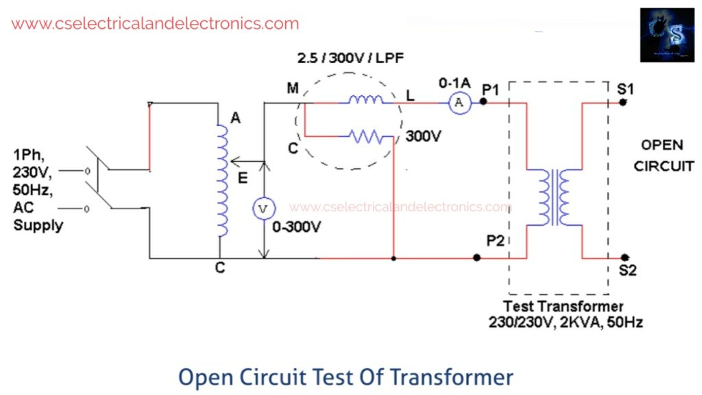
This test is conducted on the transformer to know the iron losses or no-load losses and no-load current Io which is helpful to find the parameters of Ro and Xo of the transformer. In this test the supply is given to the primary winding of the transformer which is of low voltage and the secondary winding of the transformer is open-circuited which is of high voltage.
An autotransformer is connected to the primary winding to adjust the values of low voltage and the measuring meters all are connected to the primary winding of the transformer such as an ammeter, wattmeter, and voltmeter.
The ammeter reads the no-load current which is about 2 – 5% of full load current and this ammeter is connected in series with the phase terminal of the transformer and the voltmeter is connected across the transformer that the voltmeter is connected in between the phase and neutral terminal.
Voltmeter gives the voltage of the circuit V1 and wattmeter is connected to the primary winding and this wattmeter will measure the input power Wo and these values required to find the losses which depend on the voltage only and the Copper losses are negligible in the transformer because of the less current in the transformer, i.e..,( 2-5%) and the secondary current I2=0 because of this there are no copper losses on the secondary winding.
Hence, the wattmeter gives practically no-load losses or iron losses which depend on the voltage, and these iron losses are constant in any transformer.
- Wattmeter reading =iron loss
- Wo=no-load input power
- Voltmeter reading=applied primary voltage =V1
- Ammeter reading=no load primary current =Io
- No-load input power, Wo=V1Iocos0o
- Watt less component of no-load current, Iw=Iocos0o
- Magnetizing component of no-load current.
- Im=Iosin0o=√Io^2-Iw^2
- Equivalent circuit parameters,
- Ro=V1/Iw and Xo=V1/I’m
Note: The Open-circuit test is always made on the low-voltage winding of the transformer the measurement is made on a high-voltage side, the applied voltage would be inconveniently large and the current Io would be inconveniently smaller. The open-circuit test on either side gives the same iron losses, but the metering is easy on the low voltage side.
Short circuit test or impedance test
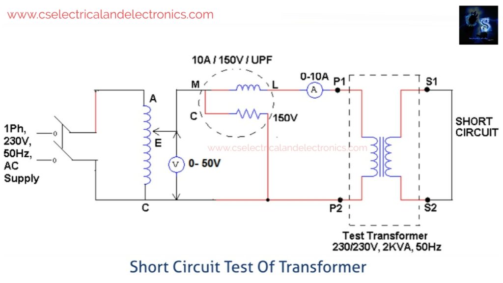
This test is conducted on the transformer to find full load copper losses and equivalent resistance Ro1 or Ro2 and equivalent reactance Xo1 or Xo2 referred to the metering side. In this test secondary winding (usually low voltage side) is short-circuited by a thick wire or strip and variable low voltage is applied.
The primary winding is of high voltage side which is connected through an autotransformer to give the rated voltage to the transformer and the all measuring meters are connected to the primary winding side only and the voltmeter measures a rated voltage of Vsc and wattmeter measures power of Wsc and ammeter measures the full current Isc.
When we apply the voltage to the circuit then the voltage to be rated voltage i.e.,(5 to 10 %) only at which it supplies a full load current and hence, the applied voltage is very small so, the iron losses are negligible and the full load copper losses can be determined in the circuit
From the data obtained by this test, the various parameters such as Ro1, Xo1, and Zo1 can be calculated as follows,
- Wattmeter reading =full load copper losses=Wsc
- Voltmeter reading=applied primary rated voltage=Vsc
- Ammeter reading =full load primary current=Isc
- Full load copper losses, Wsc=Isc^2 Ro1
- The equivalent resistance is referred to as primary, Ro1=Wsc/Isc^2
- Equivalent impedance referred to primary, Zo1=Vsc/Is
- Equivalent reactance referred to primary, Xo1=√Zo1^2-Ro1^2
- Short circuit power factor, Cos0sc=Wsc/VscIsc
Note: the short circuit test is always made on the high voltage winding of the transformer. If the measurement is made on a low voltage side, the applied voltage needed would be inconveniently low and the current would be inconveniently large.
Conclusion: these tests are conducted on the transformer to know the total losses by that we can find the voltage regulation, efficiency, parameter like resistance, reactance, impedance power factor, etc.
I hope this article may help you all a lot. Thank you for reading.
Tag: Open Circuit And Short Circuit Test On Transformer
Also, read;
- 10 Tips To Maintain Battery For Long Life, Battery Maintainance
- 10 Tips To Save Electricity Bills, Save Money By Saving Electricity
- 100 (AI) Artificial Intelligence Applications In The Automotive Industry
- 100 + Electrical Engineering Projects For Students, Engineers
- 100+ Indian Startups & What They Are Building
- 1000+ Automotive Interview Questions With Answers
- 1000+ MATLAB Simulink Projects For MTech, Engineering Students
- 2024 Is About To End, Let’s Recall Electric Vehicles Launched In 2024