Hello guys, welcome back to my blog. In this article, I will discuss switched reluctance motor, construction of switched reluctance motor, working of SRM, drive system block diagram, advantages, and disadvantages, etc.
If you require an article on some other topics then comment us below in this comment box. You can also catch me @ Instagram – Chetan Shidling.
Also, read:
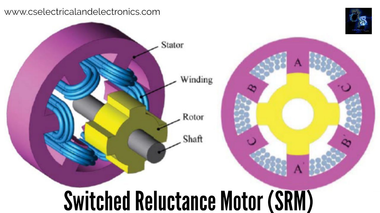
Switched Reluctance Motor (SRM)
SRM stands for switched reluctance motor which works based on the variable reluctance principle. For the operation of the SRM motor, a switching inverter is required.
Construction Of Switched Reluctance Motor

As we know all the motor consists of two main parts those are rotor and stator. In SRM motor, the stator and rotor both have projected pole which is made up of soft iron and silicon stampings. Silicon stamping will be used to reduce hysteresis losses.
The stator of the motor carries only main field winding but the router doesn’t contain any winding. Each winding of the stator is connected in series with opposite poles to increase the MMF. That is called phase winding.
The straighter winding contains 6 to 8 poles, But the rotor carries less number of poles compared to the stator. (4 to 5). If we increase the number of poles then we can get a low angle of rotation of the motor.

The shaft of the rotor will be mounted with a position sensor, this is used to determine the rotor by the control circuit. It collects the information on the position of the rotor and based on that the controller will give the input to the motor. The DC input will be connected to the converter and the output will be connected to the motor.
The rotors and sensor’s feedback wire will be connected to the controller circuit, which provides the rotor position with respect to the reference axis. At last, the controller will collect all information and gives the reference to the stator. The controller will monitor the current of the motor, to protect the motor from internal and external storage.
Working Of Switched Reluctance Motor

We already know that the magnetic flux is having a tendency to flow along the lowest reluctance path due to which the rotor always tends to align along the minimum reluctance path. This is the basic principle of the SRM motor.
Consider the phase windings of this stator be AA’, BB’, CC’. When we energized the phase winding A, Then rotor tries to align along with this phase. The A phase will be de-energized and phase B will be energized. Now the router tries to align along phase B. Then again rotor tries to align along with phase C when this C phase is energized and the B phase is de-energized.

Therefore the rotor is made to rotate in the clockwise direction by energizing the phase winding in the ABC sequence. If we want to rotate this rotor in an anticlockwise direction then phases must be energized in the ACB sequence. The particular phase winding should be energized/de-energized in synchronism with the position of the rotor. This means when the rotor aligned along with phase A, phase B should be energized, and phase A must be de-energized If you want to rotate the rotor in a clockwise direction.

Advantages Of Switched Reluctance Motor (SRM)
- System cost is low
- This motor is having high efficiency.
- It is having heat tolerance because of the absence of copper winding.
- Robust construction
- It is having a high power density
- These motors are having a constant long power range.
- These are having high speed.
- SRM motor follows the quadrant operation
Disadvantages Of Switched Reluctance Motor (SRM)
- This is a heavy motor
- The SRM drive doesn’t operate directly from AC or DC supply as it requires the current pulse.
- SRM motor is having low power.
- Creates a lot of noise.
Applications Of Switched Reluctance Motor (SRM)
- SRM motors can be used in analog electric meters.
- Used in some washing machine designs.
- These can be used in electric vehicles.
Converter Circuits For Switched Reluctance Motor
01. 2m Switch SR Converter Circuit


When the switches S1 and S2 are turned on, the current of phase A starts to increase. If the current rises above the upper limit of the hysteresis current controller, the S1 and S2 will be turned off and the current decreases, leading to the return of magnetic energy stored in the phase winding to the DC source Vdc.
02. M-switch/R-dump SR Converter Circuit


Utilizes one switch and one diode per phase. When the current rises above the upper limit, the switch S1 will be turned off. The current decreases, via the diode D1 and charging the capacitor C to the dc supply voltage and dissipating the power in the resistor R.
03. (m+1) switch/C-dump SR converter


Requires minimum switches for independent phase current control. The negative voltage across the phase winding is limited. Switch S1 is turned off when the current rises above the upper limit of the hysteresis current controller. This enables diode D1 to turn on, current decreases in the winding and is charging the capacitor C and then transferring to the DC
source Vdc.
04. 1.5m Switch SR Converter


Shares switches of each couple of nonadjacent phases. Uses three switches and three diodes for two phases. Hence, uses less than two switches for each phase and offers independent phase current control. However, topology is limited to machines having an even number of phases. The switch Sx carries the currents of phases A and C. Hence its current rating is greater than the switches S1 or S2.
Switched Reluctance Motor Speed Control
- Current Chopping Control (CCC)
- Advance Angle Control (AAC)
The speed boundary between these to control schemes is called the base speed, ωb at which the back emf is equal to the dc source voltage.
I hope this article may help you all a lot. Thank you for reading. If you have any doubts related to this article, comment below.
Also, read:
- 10 Tips To Maintain Battery For Long Life, Battery Maintainance
- 10 Tips To Save Electricity Bills, Save Money By Saving Electricity
- 100 (AI) Artificial Intelligence Applications In The Automotive Industry
- 100 + Electrical Engineering Projects For Students, Engineers
- 100+ Indian Startups & What They Are Building
- 1000+ Automotive Interview Questions With Answers
- 1000+ MATLAB Simulink Projects For MTech, Engineering Students
- 2024 Is About To End, Let’s Recall Electric Vehicles Launched In 2024
- 2026 Hackathons That Can Change Your Tech Career Forever
- 50 Tips To Save Electricity At Home, Shop, Industry, Office
- 50+ Question And Answer On The Substation, Electrical Question
- 500+ Matlab Simulink Projects Ideas For Engineers, MTech, Diploma
- 7 Ways EV Batteries Stay Safe From Thermal Runaway
- 8 Reasons Why EVs Can’t Fully Replace ICE Vehicles in India
- Active Cell Balancing Using A Flyback Converter Simulation In Matlab Simulink
- AI Artificial Intelligence Applications In Electric Vehicles | Future?
- AI Tools For Electronic Circuit Design, Which Is Best?
- All-Wheel Drive (AWD) Vs Front-Wheel Drive (FWD) Vs Rear-Wheel Drive (RWD): Which Is Better?
- Applications Of Artificial Intelligence (AI) In Renewable Energy
- Artificial Intelligence-Based Electrical Machines & Drives