Hello guys, welcome back to our blog. In this article, we will discuss what is single phase resistive load box, the construction of a single-phase resistive load box, the circuit diagram of a single-phase resistive load box, and the working of a single-phase resistive load box.
If you have any electrical, electronics, or computer science doubts, then ask questions. You can also catch me on Instagram – CS Electrical & Electronics.
Also read:
- Top 12 Fuzzy Logic Projects For Engineers And MTech Students
- Top 100+ MATLAB Simulink Projects With SLX File For Engineers
- Top 50+ Web Development Project Ideas In 2022, Web Projects
Single Phase Resistive Load Box
Introduction
- In general, many loads are available, among them resistive load is one. A resistive load is one that consumes electrical energy by using a resistance element.
- Its construction is simple as compared to the capacitive load and water rheostat load and inductive load.
- It gives accurate readings as compared to lamp load. Its operation is easy. The main drawback of the resistive load is power loss is more.
- A resistive load is generally used in laboratories and industrial applications for calibration purposes.
- Such type of load is operated at unity power factor.
Constructional Details
01. Cover
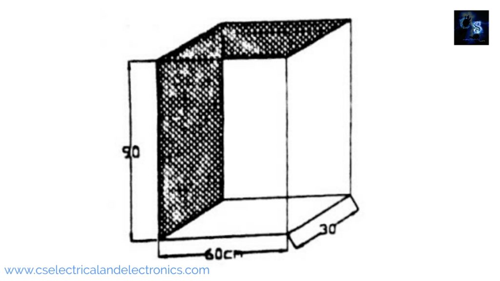
It consists of mesh and metal plates. It is used for protection of the internal part of the resistive load or housing the internal parts, i.e., porcelain tube and heating element.
02. Clamp
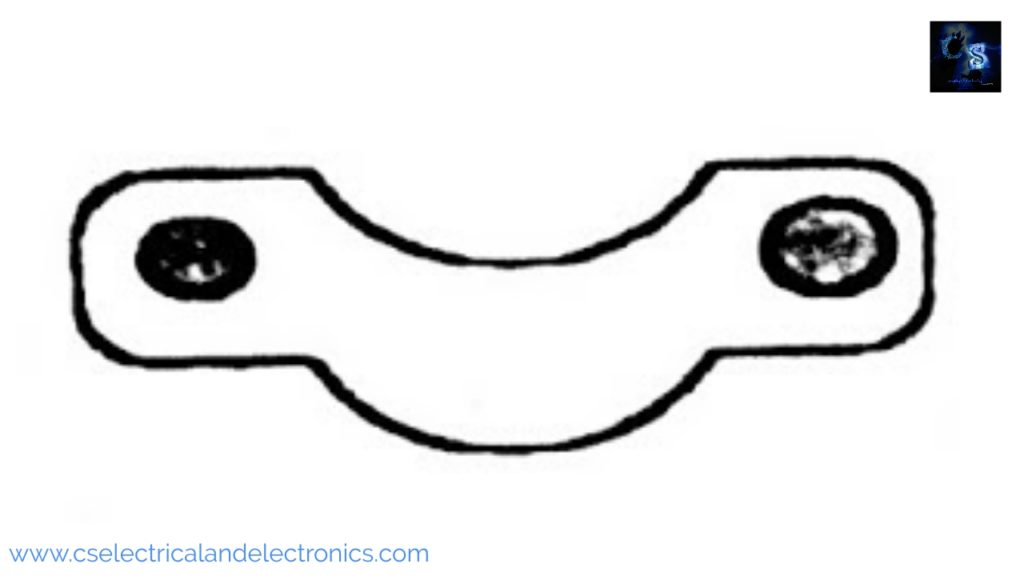
It is made up of iron. It is used to hold the porcelain tube.
03. Eureka Elements
Eureka is a resistor material. Resistor materials are those which have high resistance against the flow of electric current. Eureka is an alloy of copper (60%) and nickel (40%).
Eureka Material has the following properties:
- Its resistivity is 49 x 10-6 Ω cm.
- Specific resistivity is 1.9. Ω m
- Its melting point is 13000 C.
- Its working temperature is high.
- It does not rust or Corrosion due to air or moisture.
Application of eureka material
- Thermo-Couples
- Resistive load
- Rheostat.
- Arc lamp etc.
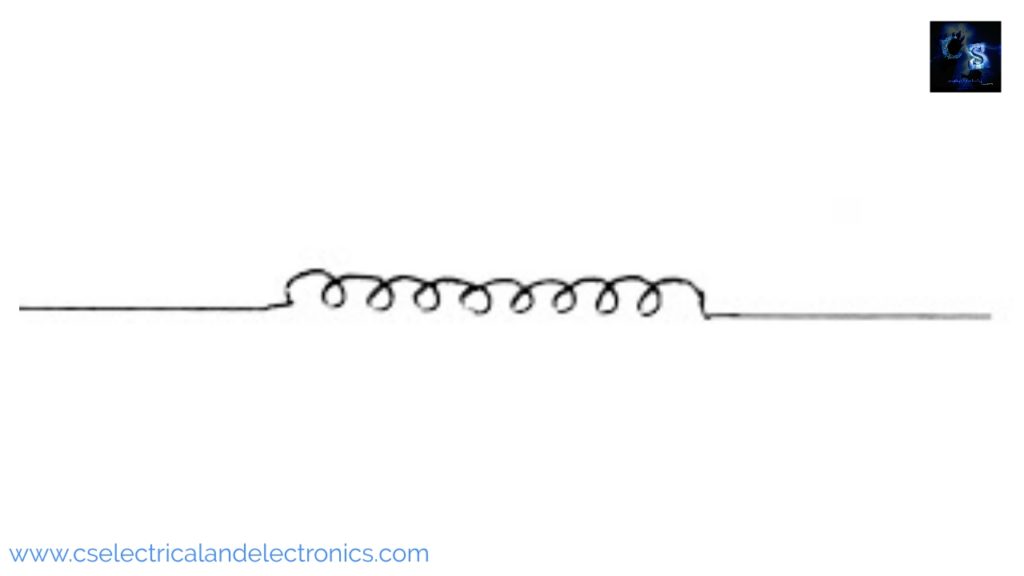
Eureka Resistance Coil
Specifications
- Material: Eureka (copper 60% and Nickle 40%)
- Voltage: 230 v.
- No of Cores: One
04. Porcelain Insulator Material
It is a common ceramic used for high-voltage and low-voltage insulators. Porcelain materials are used for the manufacture of all types of insulators. The insulation used in transmission and distribution lines, transformers, plugs, isolators, sockets, fuse and porcelain tubes, etc.
Porcelain materials have the following properties
- Its dielectric constant varies between 6 to 7.5.
- Its tensile strength varies between 0.2Kg /Cm2 to 0.55 Kg /cm2 x 103.
- Its electrical resistivity is above 10 Ωcm
- The limiting temperature varies between 10000 C to 12000 C.
- It is non-hygroscopic.
Porcelain Tube
It is a common ceramic used for low and high-voltage insulators. The raw materials are :
- Clays Kaolin (China clay).
- Filter agents – Quarts.
- Fluxing agents – Feldspar, permotite.
- Glaze-producing agent – Chalk, dolomite.
Clay gives plasticity and makes the material suitable for molding. It serves to reduce shrinkage deformation and prevent cracking during firing. Flexing agents reduce the porcelain tube.
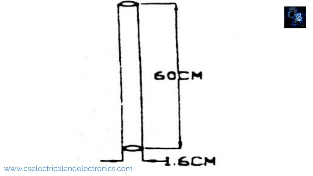
The above figure shows the simple diagram of the porcelain tube.
Applications
- Resistive load.
- Inductive load.
- Rheostat.
05. Fixed Rheostat
These are rheostat whose values are fixed. for example, we have carbon film resistors(CFR), Metal film resistors (MFR), wire wound resistors, Surface mount device resistors (SMD), and many more. Wire wound rheostat is mainly produced with alloys since pure metals have a high-temperature coefficient of resistance. However, for high temperatures, pure metals are used such as Tungsten.
The temperature coefficient is a sign of how much the resistance will change as the temperature changes. TCR is measured in units of ppm/˚C. If a manufacturer rates a resistor at 50ppm/˚C, the resistor will not change more than 50Ω in resistance for each 1MΩ of the resistors given value, for a temperature change of 1̊C. Typical alloys that are used a resistor wire are:
- Copper alloys.
- Silver alloys.
- Nickel-Chromium alloys.
- Iron Chromium alloys.
- Iron Chromium Aluminum alloys.
Specification
- 460 Ω, 0.5 Amps: 4 no’s.
- 230 Ω, 1 Amp: 3 no’s.
- 115 Ω, 2 Amps: 3 no’s.
- Material: wire wound resistor.
- Working Voltage: 230 V.
06. S.P. Toggle Switch
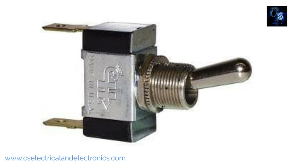
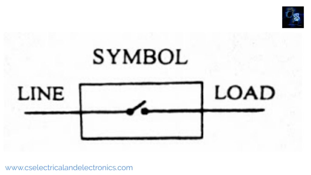
S.P. stands for a single-pole switch. It is a device that makes and breaks the circuit. It is made up of a Bakelite cover. The symbol of the S.P. TOGGLE Switch is shown in the figure.
Specifications
- Capacity: 5A.
- Working voltage: 230 V.
- No. of phase: 1ϕ.
- Material: Bakelite.
07. Fuse Element Material
The most commonly used material for the fuse element is low melting point material such as tin, zinc, copper, aluminum, and silver. The below table shows the melting points of different Fuse element materials.
| SI. No | Materials | Melting Point |
| 01 | Tin | 213.80C |
| 02 | Zinc | 4190C |
| 03 | Lead | 3270C |
| 04 | Copper | 10840C |
| 05 | Aluminum | 658.70C |
| 06 | Silver | 960.50C |
Characteristics of Fuse wire
- Low cost.
- Low melting point.
- High conductivity.
- Free from deterioration.
Specification
- Capacity: 15A.
- Working voltage: 230V.
- Type of material: Lead and tin alloy.
Fuse
A fuse is a short piece of metal inserted in the circuit, which melts when excessive current flows through it and thus breaks the circuit.
Classification of fuse
There are two types
- High voltage fuses.
- Low voltage fuses.
In low voltage fuses again two types.
- H.R.C fuses.
- Semi-enclosed rewireable fuses. (Kit-Kat type).
Kit-Kat type fuse
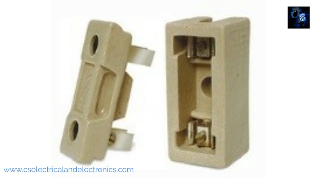
This type of fuse is used where the low value of fault current is to be interrupted. This type of fuse is almost always used in domestic installations. It is made up of base and fuse carriers. The base is made of porcelain and it carries the fixed contact to which the incoming and outgoing phase wires are connected. The above figure shows the Kit-Kat fuse.
08. D.C.C. Wire
D.C.C. stands for Double Cotton Cover. The D.C.C. wire is made up of copper wire and twisted around the cotton cover. The D.C.C. wire is used in the resistive load, connecting the Eureka coil to switch terminals.
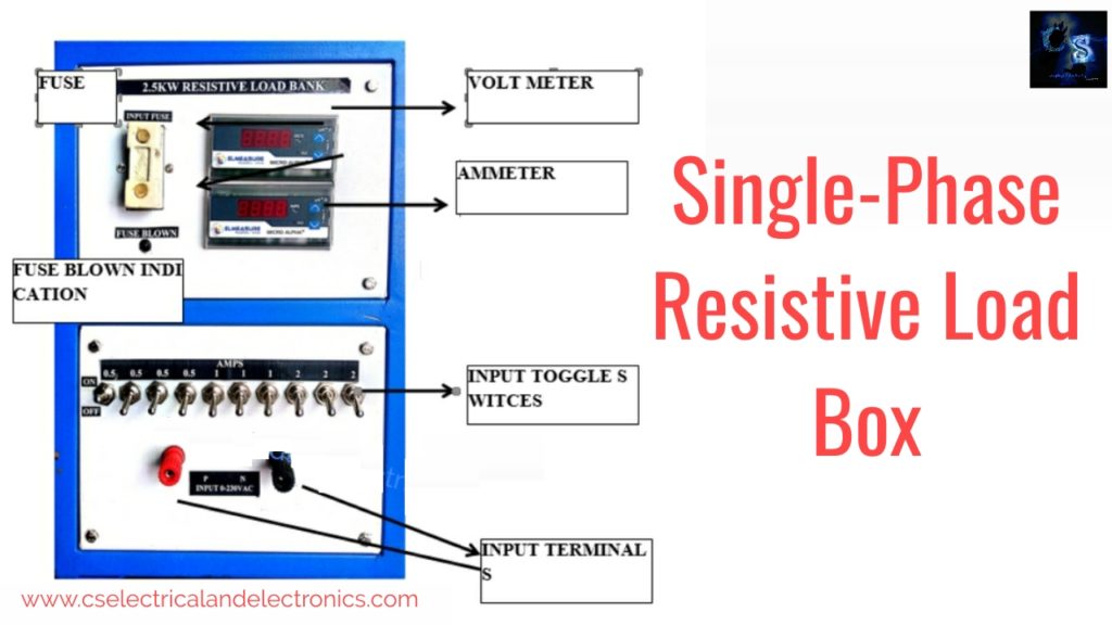
09. Assembling Of The Resistive Load Box
The figure shows the constructional details of the single-phase resistive load. It consists of the outer cover (Covering with mesh and metal plate). Switching, Fuse porcelain tube, eureka element, clamps metal strips. The outer cover is used to protect the internal parts.
A fuse is used to protect the resistive load during a short circuit or any type of fault. Switches are used to increase as well as decrease the load current. Porcelain tubes carry the eureka element. The porcelain tube is mounted on the metal strips with the clamps.
10. Ammeter
An ammeter is a measuring instrument used to measure the load current in a circuit. Electric currents are measured in amperes (A)
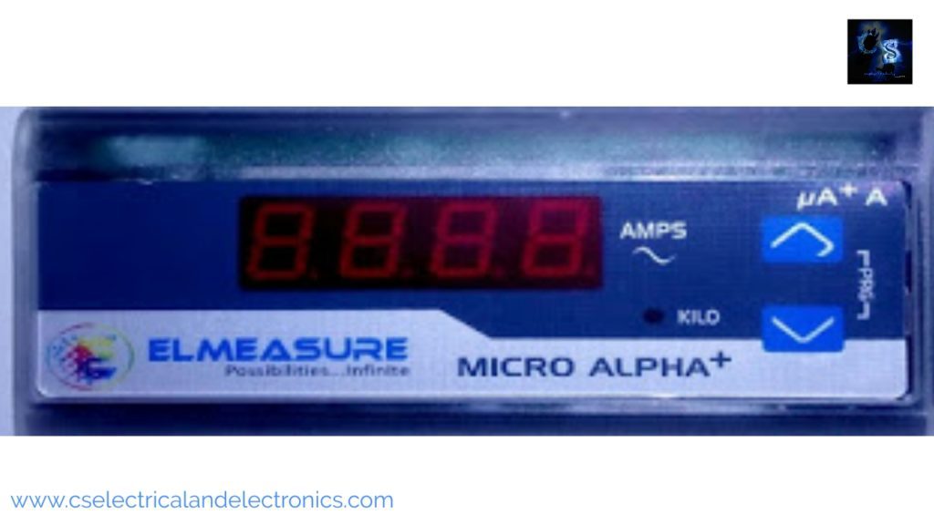
Specifications
- Type: AC
- Range: 15 Amps
11. Voltmeter
A voltmeter is an instrument used for measuring the load voltage. It is measured in volts
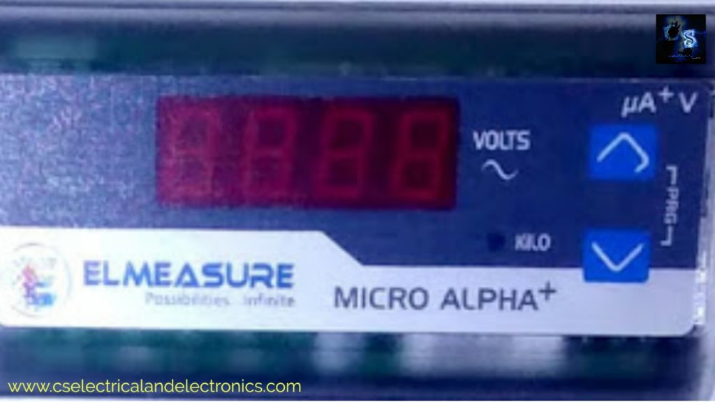
Specifications:
- Type: AC
- Range: 300 Volts
Working Of Resistive Load Box
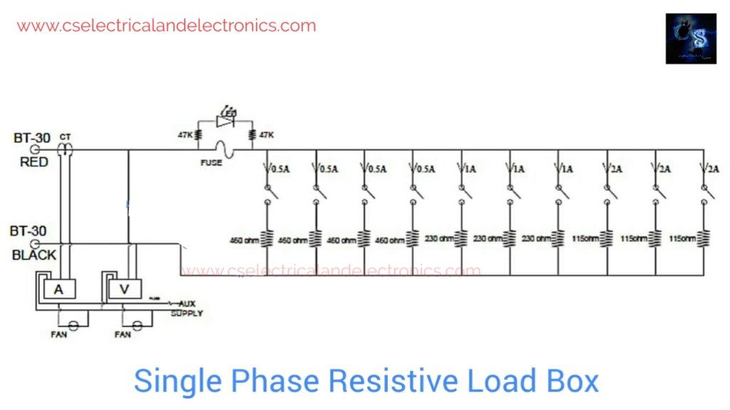
The figure shows the working of the resistive load. The Resistive load is connected across the supply, resistive load switches are kept in open. Switch “ON” the mains supply, then close the switches of the resistive load by the effect of closing the switches of the respective coil comes under the circuit, and consumes the current at its capacity. Similarly by closing switches S1, S2, S3, S4, S5, S6, S7, S8, S9, S10. By closing and opening switches of resistive load, it is possible to vary the current.
| SI.No | Switch Used | Switch Position | Current Rating In Amps |
| 01 | S1 | On | 0.5 |
| 02 | S2 | On | 0.5 |
| 03 | S3 | On | 0.5 |
| 04 | S4 | On | 0.5 |
| 05 | S5 | On | 1 |
| 06 | S6 | On | 1 |
| 07 | S7 | On | 1 |
| 08 | S8 | On | 2 |
| 09 | S9 | On | 2 |
| 10 | S10 | On | 2 |
While designing a single-phase resistive load the following important terms are used as follows.
- Electric Power: The rate at which work is done is an electric circuit is called electric power. It is represented by ‘P’. Its unit is the watt.
- Resistance: Resistance may be defined as the property of a substance that opposes the flowing of electric current through it. It is represented by ‘R’ and its unit is Ω(ohm).
- Electric current: The flow of electron in a conductor is called an electric current. It is represented by ‘I’ and its unit is Amps.
- Electric potential: The capacity of a charged body to do work. It is represented by ‘V’ and its unit is Volt.
- Specific resistance: It is also known as the resistivity of a material. It is defined as the resistance offered by the opposite face of the meter cube of the material. The unit of specific resistance is Ωmm or Ωcm or Ωmts and is denoted by ‘ρ’.
- OHMs law: The current passed through the conductor is directly proportional to the voltage and inversely proportional to the resistance of the material at a constant temperature.
Factors on which the resistance of a conductor depends are as follows
- The resistance of the conductor varies directly proportional to its length i.e. R α L
- The resistance of the conductor varies inversely proportional to its cross-sectional area i.e. R α 1/A.
- The resistance of a conductor depends upon the nature of the material.
- The resistance of the conductor depends on its temperature.
01. Instrumentation
- Digit voltmeter and ammeter to read voltage across the load and current
- LED indicator for power on.
- 3core mains cord for AUX input.
- BT-30 terminals for Load terminals.
- 15A big fuse for protection.
02. Setting up load bank for first time
The load bank is provided with a mains input cable for meters and fans auxiliary supply. This has to be connected to suitable Utility power. Please make sure that all meters and cooling fans turn on.
- Connect the load for which u want to load.
- Read the voltmeter that reads your loading supply voltage.
- Now turn on the switches with the desired loading. Continue until the required desired current and voltage. And meters will read load voltage and current.
03. Short Circuit Protection
In the event of a short circuit, while the unit is in operation, the rectifier unit will trip and will be held in the tripped position. This is indicated by the fuse blow LED. The user has to check for the external short circuit and after removing the short circuit condition the RESET the unit with all switches at off position.
04. Technical Description
The load bank employs single-phase resistive loading. The load bank input terminals are connected to the Banana terminal placed on the front panel. For the loading, the input of the load bank is connected to the digital voltmeter connected to the front panel. And for current measurement, the external current transformer is connected on the load side.
According to the CT ratio, the meter will read load current and it is placed in the front panel of the unit. For the meters to turned on, the auxiliary supply is taken from the mains. Do not use the unit without the auxiliary supply in connection.
05. Trouble Shoot
1. If the fuse is blown led is at ON, Please check the unit for any short circuit, and replace the fuse wire.
2. If a fuse is blown led is at OFF, still, the unit is not taking the desired load
- Check the switches it is working good or not,
- Check the resistors for brunt or good.
- Check the wiring as per the circuit diagram.
- If meters are not showing anything, check the aux supply.
06. Designing Of Eureka Wire Coil
Following formulas are used for solving the problems.
1) P=Vx I watts
Where,
P=power in watt
V=voltage of the coil in volt
I=current if the in amps.
2) R= V/I Ω
Where,
R=Resistance of the coil in Ω
V=Voltage of the coil in Volts
I=Current of the coil in Amps.
3) I=3.9d1.5
Where,
I=Current of the coil in Amps
d=Diameter of the coil on mm.
4) L=RA/ρmts
Where,
L =Length of the wire mts
R =Resistance of the coil in Ω
A =Area of cross-section on mm2
ρ =Specific resistive in Ω mm
Problem No 01
Design the resistance coil 230 volts, 0.5 Amps.
Given data:
- SWG of wire=33 SWG
- Current of wire(I)=0.5 Amps
- The voltage of wire(V)=230 Volts
- Specific resistivity of wire(ρ)=49 x 10-5Ω mm
Solution:
1)P = V x I watts
= 230 x 0.5 = 115 watts.
R = V/I Ω
= 230/0.5
= 460 Ω
I = 3.9d1.5
0.5 = 3.9d1.5
d1.5= 0.5/3.9
= 0.128
1.5log10d = log 0.128
1.5log10d = -0.892.
log10d = -0.892/1.5
= -0.5947
d = log-1(-0.5947)
d=0.254 mm
There fore ,
A = 0.0507 mm2(Refer table)
Therefore, L = RA/ρ
= 460 x 0.0507 / 49 x 10.5
= 47595.8 mm
= 47.5 mts.
Problem No 02
Design the resistance coil 230 v, 1 Amp
Given data:
- SWG of wire = 27 SWG
- Current of wire(I) = 1 Amps
- Voltage of wire(V) = 230 Volts
- Specific resistivity of wire(ρ) = 49 x 10-5Ω mm
Solution:
1) P = V x I Watts
230 X 1 = 230 watts
2) R = V / I Ω
= 230 / 1
= 230 Ω
3) I = 3.9d1.5
d1.5 = 1 / 3.9
= 0.256
1.5log10d = log 0.256
1.5log10d = -0.256
log10d = -0.591 / 1.5
= -0.394
d = log-1(-0.394)
d = 0.4036 mm
Therefore,
A = 0.136 mm2 (Refer table)
Therefore,
L = RA/ρ
= 230 x 0.136 / 49 x 10-5
= 63836.7 mm
= 63.8 mts.
Problem No 03
Design the resistance coil 230 v, 2 Amps
Given data:
- SWG of wire = 23 SWG
- Current of wire(I) = 2 Amps
- Voltage of wire(V) = 230 Volts
- Specific resistivity of wire(ρ) = 49 x 10-5Ω mm
Solution:
1) P = V x I watts
= 230 x 2 = 460 watts
2) R =V/I Ω
230 / 2 = 115 Ω
I = 3.9d1.5
2 = 3.9d1.5
d1.5 = 2 / 3.9
= 0.512
1.5log10d = log 0.512
1.5log10d = -0.290
log10d = -0.290
1.5
= -0.1938
d = log-1(-.1938)
d = 0.64 mm
Therefore,
A = 0.292 mm2(Refer table)
Therefore,
L = RA / ρ
= 115 x 0.290 / 49 x 10-5
= 68530.6 mm
= 68.5 mts.
Standard Wire Guage Table
| SWG | Diameter(mm) | Area(mm) | SWG | Diameter(mm) | Area(mm) |
| 01 | 7.62 | 45.6 | 21 | 0.813 | 0.519 |
| 02 | 7.01 | 38.6 | 22 | 0.711 | 0.397 |
| 03 | 6.40 | 32.2 | 23 | 0.610 | 0.292 |
| 04 | 5.89 | 27.3 | 24 | 0.559 | 0.245 |
| 05 | 5.38 | 22.8 | 25 | 0.508 | 0.203 |
| 06 | 4.88 | 18.7 | 26 | 0.457 | 0.164 |
| 07 | 4.47 | 15.7 | 27 | 0.417 | 0.136 |
| 08 | 4.06 | 13.0 | 28 | 0.376 | 0.111 |
| 09 | 3.66 | 10.5 | 29 | 0.345 | 0.0937 |
| 10 | 3.25 | 8.3 | 30 | 0.315 | 0.779 |
| 11 | 2.95 | 6.82 | 31 | 0.295 | 0.0682 |
| 12 | 2.64 | 5.48 | 32 | 0.274 | 0.0682 |
| 13 | 2.34 | 4.29 | 33 | 0.254 | 0.0591 |
| 14 | 2.03 | 3.24 | 34 | 0.234 | 0.0429 |
| 15 | 1.83 | 2.63 | 35 | 0.213 | 0.0357 |
| 16 | 1.63 | 2.07 | 36 | 0.193 | 0.0293 |
| 17 | 1.42 | 1.59 | 37 | 0.173 | 0.0234 |
| 18 | 1.22 | 1.17 | 38 | 0.152 | 0.0183 |
| 19 | 1.32 | 0.811 | 39 | 0.132 | 0.0137 |
| 20 | 0.914 | 0.657 | 40 | 0.122 | 0.0117 |
Conclusion
The power factor of the load is unity and it operates on 230 v,1φ, A.C, and its rating is 2.4 OR 1 KW.
Performance Of Result
| Coil No | Designed Current Rating | Measured Current |
| S1 | 0.5 | 0.49 |
| S2 | 0.5 | 0.52 |
| S3 | 0.5 | 0.48 |
| S4 | 0.5 | 0.51 |
| S5 | 1 | 1 |
| S6 | 1 | 1 |
| S7 | 1 | 1 |
| S8 | 2 | 2 |
| S9 | 2 | 1.95 |
| S10 | 2 | 1.94 |
Advantages Of Single Phase Resistive Load Box
- Less cost.
- Less Weight.
- less size.
- Less time requires assembling.
- Require less space.
- Deliver more power.
- Higher efficiency.
- Easier to install.
- Easy transportation and installation.
- Easy to repair.
- Easy assembling.
Disadvantages of single-phase resistive load box
- The greater cost of standby Units.
- increased cost and inconvenience of repairs.
- The designed load cannot be extended.
Estimation And Costing Of Materials
| SI.No | Name of the equipment’s | Prize |
| 01 | Fixed coils | 4,500 |
| 02 | Cover with wheels | 2,000 |
| 03 | Toggle switches | 200 |
| 04 | Voltmeter | 1,200 |
| 05 | Ammeter | 1,200 |
| 06 | Fan’s | 1,200 |
| 07 | Fuse | 100 |
| 08 | Indicator | 100 |
| 09 | CT | 250 |
| 10 | BT-3D | 80 |
| 11 | 47K resistance | 40 |
| 12 | Wires | 800 |
| 13 | Labour charge | 2,500 |
| 14 | Testing and demo | 1,780 |
| 15 | Painting | 150 |
| 16 | GST | 700 |
| Total | =17,100 |
I hope this article may help you all a lot.
Tag: Single Phase Resistive Load Box, Construction, Working, Applications.
I think now you are clear with single phase resistive load box. Also read,
- 2000+ Embedded Systems Interview Question Bank
- Visually Explained Single Pair Ethernet Protocol
- NVIDIA’s LocateAnything: The AI Breakthrough That Makes Object Detection 10x Faster
- All Companies For Embedded Engineers In India
- Tata Sierra EV: The Iconic SUV Returns To Shape India’s Electric Future
- Roadmap To Automotive Industry Roles
- These 10 Embedded Technologies Once Powered the World — But Were Later Banned, Restricted, or Phased Out
- Elon Musk’s AI Satellites: Could Millions of Intelligent Spacecraft Change the Future of Humanity?