What Actually Happens When You Press the Accelerator? 🚗⚡
You press the pedal and the car doesn’t simply “go faster.” A chain of sensors, controllers, networks, power electronics and mechanical parts springs into action, all within milliseconds. This guide follows that chain step by step, for petrol, diesel and electric vehicles.
1. The Big Picture: A Real-Time Control Loop
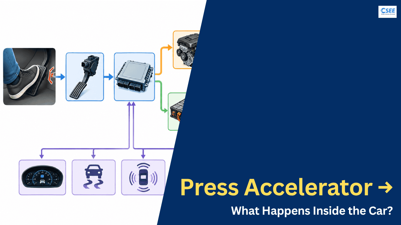
Every accelerator press begins a loop that runs many times per second: sense → decide → act → measure → correct. The driver is one input. The controller also listens to vehicle speed, gear, engine or motor speed, battery state, temperature, wheel slip and stability systems before it decides what to do.
2. Step 1: The Pedal Sensor
Older cars used a steel cable from pedal to throttle. Modern cars use drive-by-wire: the pedal carries an Accelerator Pedal Position Sensor (APPS), usually a Hall-effect or potentiometer type. Two or three independent tracks measure the same movement, and the ECU constantly compares them. If they disagree beyond a tolerance, it assumes a fault and limits power (limp mode).
| Feature | Why it matters |
|---|---|
| Dual or triple sensor tracks | Redundancy. A single broken wire cannot cause unintended acceleration. |
| Different slopes or voltages per track | Lets the ECU detect short circuits and cross-wiring. |
| Contactless Hall-effect sensing | No wear from rubbing parts, so longer life. |
| Idle / kickdown switch or detent | Gives the driver a tactile “full throttle” feel and confirms extremes. |
The output is typically an analog voltage such as 0.5 V (released) to 4.5 V (fully pressed), or a digital PWM/SENT signal. The ECU converts it into a percentage: 0% to 100% pedal.
3. Step 2: The Controller Decides
The controller is the Engine Control Unit (ECU) in a combustion car, or the Vehicle Control Unit (VCU) in an EV. Pedal percentage is passed through a pedal map, a lookup table that converts pedal position and speed into a driver torque demand. It is not linear on purpose: gentle at the start for smooth driving, stronger later for overtaking.
| Pedal % | Eco mode demand | Normal mode demand | Sport mode demand |
|---|---|---|---|
| 10% | 4% | 8% | 12% |
| 30% | 15% | 28% | 38% |
| 50% | 32% | 50% | 62% |
| 80% | 65% | 82% | 92% |
| 100% | 85% | 100% | 100% |
Illustrative values of requested torque as a share of available torque. Real maps are 3D, also depending on speed or RPM.
Inputs the controller weighs
4. Step 3A: Petrol and Diesel Cars
The ECU turns the torque demand into three main actions.
- Air. In a petrol engine the electronic throttle body’s motor opens a butterfly valve. More air enters the intake manifold. Turbocharged engines also adjust boost through the wastegate or variable-geometry vanes. Diesels have no throttle to speak of; power is mostly set by fuel.
- Fuel. A mass air flow or manifold pressure sensor tells the ECU how much air arrived. It calculates fuel to hit the target air-fuel ratio (about 14.7:1 for petrol, which is stoichiometric) and opens the injectors for a precise number of milliseconds. Diesel injectors work at very high rail pressure, often over 1,500 bar.
- Ignition. In a petrol engine the ECU fires each spark plug at the best crank angle. Advance the timing for efficiency, retard it if the knock sensor hears detonation. Diesel relies on compression ignition, so injection timing plays this role.
The combustion pushes pistons, the crankshaft spins, and torque passes through the clutch or torque converter, gearbox, driveshaft, differential and axles to the wheels. Sensors on the crankshaft, camshaft, oxygen (lambda) and knock keep the loop closed.
| Actuator | Controlled by | Effect |
|---|---|---|
| Throttle valve | ECU via motor | Airflow, torque |
| Fuel injectors | ECU pulse width | Fuel quantity |
| Ignition coils | ECU timing | Efficiency, knock control |
| Turbo wastegate / VGT | ECU duty cycle | Boost pressure |
| Transmission | TCU | Gear ratio, shift feel |
5. Step 3B: Electric Vehicles
An EV skips air, fuel and spark. The VCU converts the torque demand into a request for the motor controller, which in turn commands the inverter. Torque in an electric motor is roughly proportional to current, so controlling current means controlling torque.
What the inverter and controller do
The inverter uses power switches (IGBTs or SiC MOSFETs) turned on and off thousands of times per second (PWM) to build three sine-like AC currents. A technique called field-oriented control (FOC) splits motor current into a torque-producing part and a flux-producing part, using the rotor position from a resolver or encoder. Change the current, and the torque follows almost instantly, often within a few milliseconds. That is why EVs feel so responsive.
Regeneration
When you lift off, the VCU can command negative torque. The motor acts as a generator, sending energy back into the battery. Many EVs blend this with friction brakes so the driver feels one consistent pedal response.
6. Combustion vs Electric Response
| Aspect | Petrol / Diesel | Electric |
|---|---|---|
| Torque delivery | Builds with airflow, RPM and boost | Near-instant from zero speed |
| Key actuator | Throttle, injectors, spark | Inverter switching |
| Response delay | Tens to hundreds of ms (turbo lag) | Few ms |
| Gearbox | Multi-speed | Usually single-speed |
| Deceleration recovery | None, only engine braking | Regenerative braking |
| Main limiters | Knock, temperature, emissions | Battery, inverter and motor limits |
7. Communication Networks
These controllers are separate computers, so they talk over in-vehicle networks. The most common is CAN (Controller Area Network), with faster options like CAN FD and Automotive Ethernet for demanding systems. Every message has an ID and a small payload, repeated every few milliseconds.
| Message | From | To | Typical rate |
|---|---|---|---|
| Pedal position | Pedal module | ECU / VCU | 5-10 ms |
| Torque request | VCU | Motor controller / engine ECU | 5-10 ms |
| Wheel speeds | ABS module | VCU, ESC, TCU | 10-20 ms |
| Battery limits | BMS | VCU | 10-100 ms |
| Torque reduction | Stability control | VCU / ECU | As needed |
8. Safety, Traction and Stability
While you accelerate, other systems watch over you:
Automotive functional safety standards (ISO 26262) guide how these features are designed, with redundant sensors, monitoring processors and defined safe states.
9. A Timeline of One Press
| Time | Event |
|---|---|
| 0 ms | Foot moves the pedal; sensor voltages change. |
| ~1-5 ms | ECU/VCU samples and validates the signals. |
| ~5-10 ms | Pedal map and limits produce a torque request. |
| ~10 ms (EV) | Inverter changes phase currents; motor torque rises. |
| ~50-200 ms (ICE) | Throttle opens, air fills the manifold, boost builds, combustion torque rises. |
| Continuous | Wheel speed, slip and temperatures feed back to correct the output. |
10. Summary
- The pedal sends a torque request, not a direct command to a valve.
- Redundant sensors and a controller check and interpret it using speed, gear, temperature and battery data.
- Combustion cars manage air, fuel and spark; EVs manage inverter current.
- Networks like CAN connect all controllers in real time.
- Traction, stability and safety functions can adjust or override the request.
So the simple accelerator pedal really is the start of a complex control loop involving sensors, ECUs, communication networks, power electronics, engines or motors, and finally, your wheels moving. It is one of the clearest examples of automotive software and hardware working together. 🚗⚡
Also, read:
- Press Accelerator → What Happens Inside the Car?
- What Does TOPS Mean In AI Chips?
- The Future of Communication: Neuralink VOICE
- Top 10 Tools to Design ADAS and Autonomous Driving Systems Virtually
- What Is The Main Aim Of Semicon 2.0?
- 20 Advanced Coursera Courses for Embedded Engineers That Can Lead to High-Paying Careers
- E/E Architecture Is Changing: From Distributed ECUs to Zonal Architecture
- Embedded C vs C++: Which Should Embedded Engineers Learn?