Hello guys, welcome back to our blog. In this article, we will discuss UART working, a diagram of UART, applications, advantages, and disadvantages, and I will also share how to write code for UART.
If you have any electrical, electronics, and computer science doubts, then ask questions. You can also catch me on Instagram – CS Electrical & Electronics.
Also, read:
- Top 20 AUTOSAR Interview Questions For AUTOSAR Engineers
- Products Manufactured By Infineon Technologies Company In Detail
- What Is FreeRTOS, Purpose, Working, Configuration, Applications
UART ~ Universal Asynchronous Receiver Transmitter
UART stands for Universal Asynchronous Receiver Transmitter, it is mainly used for serial communication and UART will be like IC (Integrated Circuits) on the microcontrollers. It is not a communication protocol, but it is one of the simple and commonly used hardware for serial communication. It is used in many electronic devices like Bluetooth modules, wireless communication, GPS, Arduino, etc.
Almost all microcontrollers like Arduino, Raspberry Pi, and other controllers have a dedicated UART IC and the main reason for adding UART in controllers is because of serial communication and it requires only two wires i.e., one for sending data and another one for receiving the data.
Before explaining UART, I will explain the difference between serial communication and parallel communication. In serial communication, the data is transferred one by one in a serial manner and the wires required are less in serial communication. In parallel communication, the data is transmitted at once and the wires required in parallel communication are more. The below image will explain to you in an easy way.
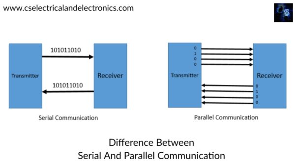
This was the difference between serial communication and parallel communication. Well, now let’s discuss UART. Universal Asynchronous Receiver Transmitter or UART is known for serial communication. It performs parallel to serial data conversion at the transmitter side and serial to parallel data conversion at the receiver side as shown in the below image.
This UART is universal because the data speed, transfer speed, etc are configurable. The UART is like a bridge between the controller or processor and serial communication protocols like USB and RS-232. In UART, letter A stands for asynchronous i.e., there is no clock signal present to synchronize or validate the data transmitted from the sender or transmitter and received by the receiver.
Well, guys, if the clock signal is not present, then how does the receiver know when to read the information or data? Well, guys, UART uses special bits at the starting and ending of each data word to synchronize the transmitter and receiver.
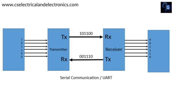
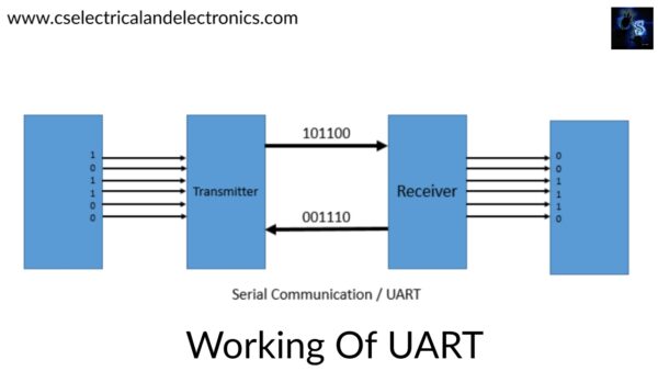
UART works in this manner. The UART at the sending side receives parallel data from the controller and converts the parallel data into serial data, then the serial data is transmitted via serial communication protocol like USB, RS 232, etc. The pin on UART which is transmitting serial data is called Tx. On the receiver side, the Universal Asynchronous Receiver Transmitter receives the serial data, then converts the serial data into parallel data, and then gives it to the controller or other devices. The UART pin at the receiver side is called Rx.
Working Of UART
In UART, the data is transmitted asynchronously i.e., there is no clock signal or other time signal present between the sender and receiver. Instead of this, the Universal Asynchronous Receiver Transmitter uses some special bits called Start bit and Stop bit. The Start and Stop bits are added to the actual data packet at the start and end. These extra bits allow the UART on the receiving side to identify the actual data.
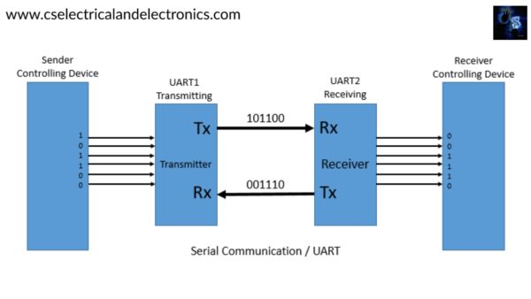
The above images show the Universal Asynchronous Receiver Transmitter connection. The UART1 transmitting receives the parallel data from the controlling device. The controlling device may be anything like a CPU, microcontroller, memory, etc.
The data received from the controlling device is parallel data. UART1 adds Start, Parity, and Stop bits to this data and converts it to the data packet. The data packet is then converted from parallel to serial with a shift register and is sent or transmitted bit by bit from the Tx pin.
The UART2 receives the serial data at the pin Rx and identifies the actual data by finding Start and Stop bits. The parity bit is used to check data quality and whether it contains an error or not. After separating the bits such as Start, Parity, and Stop from the data packet, the data is then converted to parallel with the shift register. This data which is in parallel is sent to the controlling device.
Data Packet-In UART
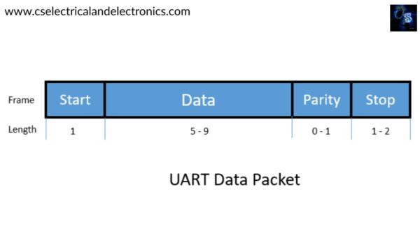
Start Bit: It is added before the actual data. When the transmission line is not sending any data, it is kept high. When transmitting the data, the Start bit is made low. By this, the receiver identifies the change from high to low on the data line and starts reading the actual data.
Stop Bit: It indicates the end of the data packet. It is normally 2 bits long. But only one bit is used, to end the transmission, the UART maintains the data line at voltage high (1).
Parity Bit: It will check whether the data received is correct or not. It is just optional and commonly not used.
Data Bits: It contains the actual data which is to be utilized by the controlling device.
Applications Of UART
- In Arduino & Raspberry Pi
- Wireless Communication
- USB
- Bluetooth Communication
- Laptops or PC
Advantages Of UART
- It only requires two wires for sending and receiving.
- A clock is not required.
- Less power consumption.
- It has a parity bit to check quality.
Disadvantages Of UART
- The data frame size is limited.
- The speed of data transfer is less when compared to parallel communication.
- A proper baud rate should be selected.
Baud Rate: The baud rate means the speed at which the data is transmitted is called baud rate. The standard baud rates are 9600 bps, 4800 bps, 19200 bps, etc. The 9600 bps is most commonly used.
Arduino Code For UART
void setup() {
  pinMode(8, INPUT_PULLUP); // set push button pin as input
  pinMode(13, OUTPUT);      // set LED pin as output
  digitalWrite(13, LOW);    // switch off LED pin

  Serial.begin(9600);       // initialize UART with baud rate of 9600 bps
}

void loop() {
  if (Serial.available()) {
    char data_rcvd = Serial.read();   // read one byte from serial buffer and save to data_rcvd

    if (data_rcvd == '1') digitalWrite(13, HIGH); // switch LED On
    if (data_rcvd == '0') digitalWrite(13, LOW);  // switch LED Off
  }

  if (digitalRead(8) == HIGH) Serial.write('0');    // send the char '0' to serial if button is not pressed.
  else Serial.write('1');                           // send the char '1' to serial if button is pressed.
}
This was about Universal Asynchronous Receiver Transmitter. I hope this article may help you all a lot. Thank you for reading.
Also, read:
- NVIDIA’s LocateAnything: The AI Breakthrough That Makes Object Detection 10x Faster
- All Companies For Embedded Engineers In India
- Tata Sierra EV: The Iconic SUV Returns To Shape India’s Electric Future
- Roadmap To Automotive Industry Roles
- These 10 Embedded Technologies Once Powered the World — But Were Later Banned, Restricted, or Phased Out
- Elon Musk’s AI Satellites: Could Millions of Intelligent Spacecraft Change the Future of Humanity?
- MATLAB M-Scripting Questions Explained Visually | Beginner To Advanced
- China’s Underwater Data Centers: The Future Of AI Computing Beneath The Sea