Hello guys, welcome back to our blog. In this article, we will discuss the different types of logic gates in digital electronics, IC numbers of logic gates, truth tables, diagrams, and the working of logic gates.
If you have any electrical, electronics, and computer science doubts, then ask questions. You can also catch me on Instagram – CS Electrical & Electronics.
Also, read:
- CAN Protocol Tutorial, Working, Frames, Interview Q’s, Errors
- Top 16 Robots That Will Change The World, Humanoid Robots
- What Are Parasitic Capacitance And Inductance, Causes, Avoid
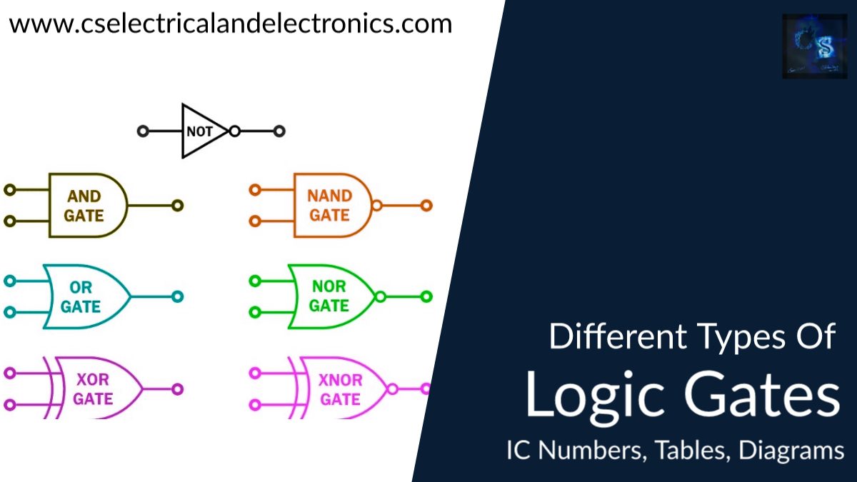
Types Of Logic Gates
A logic gate is an electronic device which is performing logical operations. The inputs of the logic gates having in binary form(0,1) and get the output in binary form. Logic gates are specially implemented using diodes or thyristors behaving as electronic switches. With amplification, logic gates are often cascaded in an equivalent way that Boolean functions are often composed, allowing the event of a physical model of all of the Boolean logic, and hence all of the logarithms and arithmetic which will be described with boolean logic.
There are seven sorts of logic gates present in electronic devices they are NOT, OR, AND, NAND, NOR, XOR, and X-NOR gates. Altogether seven sorts of gates, there are basic gates, universal gates, and exclusive gates. Now, I will discuss the types of logic gates.
Basic Gates
There are three types of basic gates present in digital electronics they are NOT, OR, AND gates. Each gate has its own working functionality. These basic gates are used for basic functions here the working of these gates.
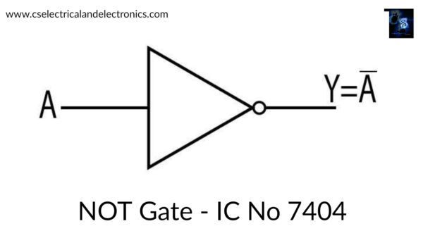
01. NOT Gate
In digital electronics, we call NOT gate an inverter. Because NOT gate gives the output an inversion to the input. The IC number of NOT Gate is 7404.
| Input=(A) | Output=(Not A) |
| 0 | 1 |
| 1 | 0 |
An inverter circuit output represents the inversion to its input. Its major purpose is to invert the input signal applied. If the given input is low value then the output comes with a high value and vice versa. The construction of a NOT gate is very easy and it requires few devices to design a NOT gate. Hence, limited power is needed to operate the NOT gate.
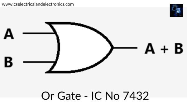
02. OR Gate
An OR Gate is a basic gate used in digital electronics. It gives the output as the addition of two inputs. The IC number of the OR Gate is 7432.
| Inputs A B | Output =A+B |
| 0 0 | 0 |
| 0 1 | 1 |
| 1 0 | 1 |
| 1 1 | 1 |
The OR gate is a digital logic gate that combines both inputs and offers unique output. If one of the inputs of the OR gate is high then the output is also high. If two inputs are low then the output is low and if two inputs are high then the output also high. This is the total logical operation of the OR gate.
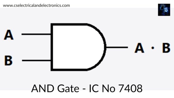
03. AND Gate
An AND gate is a fundamental digital logic gate. It gives the output by multiplying both inputs. The IC number of AND Gate is 7408.
| Inputs A B | Output= A.B |
| 0 0 | 0 |
| 0 1 | 0 |
| 1 0 | 0 |
| 1 1 | 1 |
AND gate having two inputs and one output. If one of the inputs in the AND gate is low then the output is low. If the inputs are high then the output is high.
Universal Gates
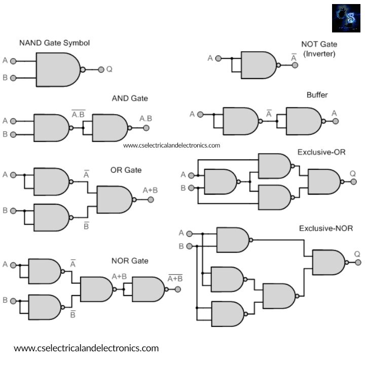
There are two types of universal gates present in digital electronics they are NAND and NOR gates. The reason for calling these gates the universal gate is that by using universal gates we can implement any gates may be it basic gates or exclusive gates. Each universal gate has its own logical function. Here is the working functionality of universal gates. Universal gates come under types of logic gates.
04. NAND Gate
NAND gate is designed by the combination of AND, & NOT gates. Bubbled OR gate is called a NAND gate. The IC number of the NAND Gate is 7400.
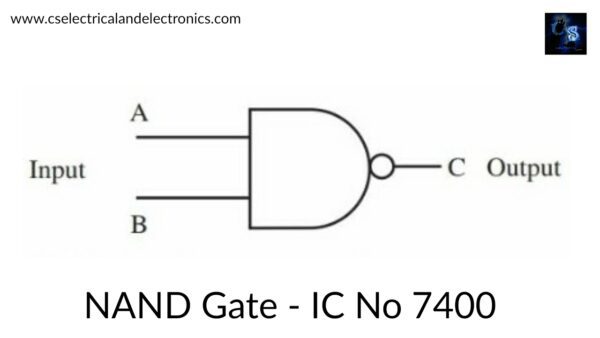
| Inputs A B | Output=(A.B)’ |
| 0 0 | 1 |
| 0 1 | 1 |
| 1 0 | 1 |
| 1 1 | 0 |
If one of the inputs in the NAND gate is low then the output is high. If the two inputs of the NAND gate are high then the output is low. The output of the AND gate is a complement to the NAND gate. NAND gate is the universal gate so, by using one NAND gate we implement one NOT gate, by using two NAND gates we implement one AND gate, by using three NAND gates we implement one OR gate, by using four NAND gates we can implement one NOR, X-OR gates and by using of five NAND gates we implement one X-NOR gate.
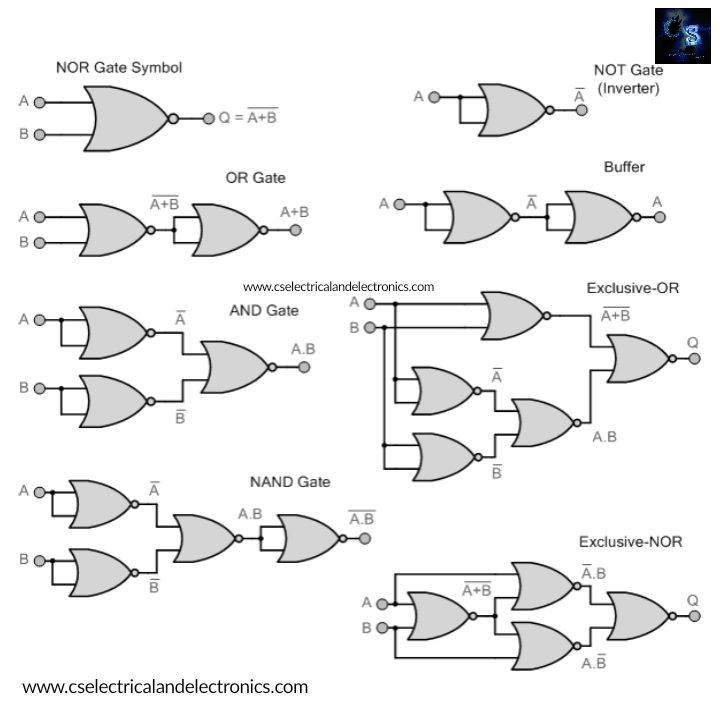
05. NOR Gate
NOR gate is designed by the combination of NOT, & OR gate. Bubbled AND is called the NOR gate. The IC number of the NOR Gate is 7402.

| Inputs A B | Output=(A+B)’ |
| 0 0 | 1 |
| 0 1 | 0 |
| 1 0 | 0 |
| 1 1 | 0 |
If one of the inputs in the NOR gate is high then the output of the NOR gate is low. If both the inputs are low then the output is high. The output of the OR gate is a complement to the NOR gate. NOR gate is the universal gate so, by using one NOR gate we implement one NOT gate, by using two NOR gates we implement one OR gate, by using three NOR gates we implement one AND gate, by using four NOR gates we can implement one NAND, X-NOR gates and by using of five NOR gates we implement one XOR gate.
Exclusive Gate
There are two types of exclusive gates that exist in digital electronics they are X-OR and X-NOR gates. The exclusive gate will also come under types of logic gates.
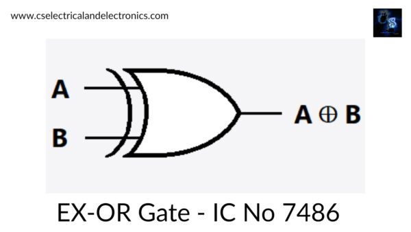
06. X-OR Gate
X-OR gate we generally call it Ex-OR and exclusive OR in digital electronics. The IC number of the X-OR Gate is 7486.
| Inputs A B | Output={A (X-OR) B} |
| 0 0 | 0 |
| 0 1 | 1 |
| 1 0 | 1 |
| 1 1 | 0 |
If the inputs of the X-OR gate have odd numbers of ones then the output of the X-OR gate is high. If both inputs are the same value then the output is low. We can design the X-OR gate by using universal gates and basic gates because sometimes the X-OR gates are not available. So, a circuit that implements the same function can be designed from other available gates.
07. X-NOR Gate
The X-NOR gate is generally we call an Ex-NOR and the Exclusive NOR gate.
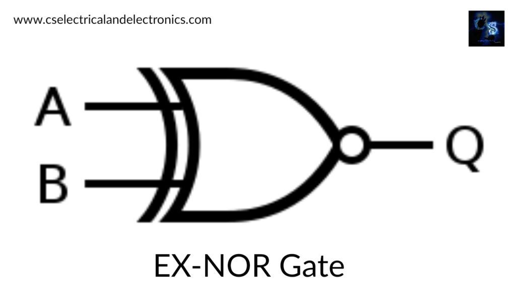
| Inputs A B | Output={A(X-NOR)B} |
| 0 0 | 1 |
| 0 1 | 0 |
| 1 0 | 0 |
| 1 1 | 1 |
If the inputs of the X-NOR gate have an odd number of ones then the output is low. If both inputs of the X-NOR gate have the same then the output is high. If there is no availability of an X-NOR gate then there is a chance to implement the X-NOR gate by using basic and universal gates.
These are the logic gates present in digital electronics. Every logic gate has its own logic function. Mainly the logic gates are used to determine the logical operations for complicated circuits and to understand each logic gate function in a better manner.
I hope this article helps you all to understand the concept of Logic gates in digital electronics. Thank you for reading. If you have any doubts related to this article “types of logic gates”, then comment below in the comment box.
Also, read:
- 10 Free ADAS Projects With Source Code And Documentation – Learn & Build Today
- 100 + Electrical Engineering Projects For Students, Engineers
- 100+ Indian Startups & What They Are Building
- 1000+ Automotive Interview Questions With Answers
- 1000+ Electronics Projects For Engineers, Diploma, MTech Students
- 1000+ MATLAB Simulink Projects For MTech, Engineering Students
- 2026 Hackathons That Can Change Your Tech Career Forever
- 50 Advanced Level Interview Questions On CAPL Scripting