Hello guys, welcome back to our blog. Here in this article, we will discuss the top model-based development using MATLAB Simulink interview questions, and I am sharing this list based on my experience as I have more than 10+ interviews on MBD.
Ask questions if you have any electrical, electronics, or computer science doubts. You can also catch me on Instagram – CS Electrical & Electronics.
Also, read:
- What Is J1939 In Automotive, Its Working, Purpose, Applications
- Difference Between CC, LIM, ACC, And ACCP In Automotive
- Why PMSM Is Very Popular In Electric Vehicles?
Top Model-Based Development Using MATLAB Simulink Interview Questions
01. What is the use of a solver in MATLAB Simulink?
Ans. A solver is used in MATLAB Simulink to calculate the time-dependent behavior of dynamic systems. The differential equations describing the system are solved numerically, allowing it to ascertain how the system states change as time steps pass. Because they can handle discrete, hybrid, and continuous systems, solvers are crucial for accurately simulating a wide range of model types.
02. What are the different types of solvers used?
Ans. In MATLAB Simulink, there are two main types of solvers: continuous and discrete. Within these categories, there are various specific solvers optimized for different types of simulations.
Continuous Solvers: Continuous solvers are used for models with continuous states, typically described by differential equations.
01. Fixed-Step Solvers:
- ODE1 (Euler): Simple, but less accurate.
- ODE2 (Heun): Improved accuracy over ODE1.
- ODE3 (Bogacki-Shampine): Balances accuracy and performance.
- ODE4 (Runge-Kutta): More accurate, commonly used.
- ODE5 (Dormand-Prince): Higher accuracy.
- ODE8 (Dormand-Prince): Very accurate, for precise simulations.
02. Variable-Step Solvers:
- ODE45 (Dormand-Prince): Most common, good balance of speed and accuracy.
- ODE23 (Bogacki-Shampine): Efficient for moderately stiff problems.
- ODE113 (Adams-Bashforth-Moulton): Efficient for problems requiring stringent accuracy.
- ODE15s (Gear’s method): For stiff problems.
- ODE23s (Rosenbrock): For stiff problems, but less efficient than ODE15s.
- ODE23t (Trapezoidal rule): For moderately stiff problems, supports state events.
- ODE23tb (Trapezoidal rule): For stiff problems, combines efficiency and robustness.
Discrete Solvers: Discrete solvers are used for models with discrete states, typically described by difference equations.
01. Fixed-Step Discrete Solver: For models with fixed-step, discrete state updates.
02. Variable-Step Discrete Solver: Not commonly used as discrete systems typically operate at fixed time steps.
Specialized Solvers
01. Simscape Solvers:
- Used for physical modeling (e.g., electrical, mechanical systems).
- Local solvers for each physical network.
- Global solvers for the entire model.
02. S-Function Solvers: Custom solvers are defined using S-functions for specialized requirements.
These solvers are selected based on the characteristics of the model, such as stiffness, accuracy requirements, and computational efficiency.
03. What is the difference between stateflow and Simulink?
Ans. While Simulink is used to model and simulate dynamic systems with continuous or discrete-time dynamics using block diagrams, Stateflow is used to build and simulate state machines and control logic. To manage intricate logic and event-driven behavior inside a Simulink model, Stateflow interfaces with Simulink.
04. What is the difference between Simscape and Simulink?
Ans. Using a physical, acausal modeling method, Simscape is used to describe and simulate physical systems with real-world components, such as electrical, mechanical, and hydraulic systems. On the other hand, block diagrams that depict mathematical operations and algorithms are utilized in Simulink to model and simulate dynamic systems and control systems. Simulink and Simscape can be integrated to create a more thorough simulation of physical systems.
05. What is the triggered and enabled subsystem?
Ans. In Simulink, a triggered subsystem operates when a predetermined trigger condition—typically an input signal—is satisfied. It is perfect for effectively modeling behaviors that are dependent on occurrences.
While an enabled subsystem runs constantly, its outputs change in response to an enabling signal. As a result, the subsystem’s computation of outputs can be dynamically controlled to adjust to changing simulation settings.
06. Which type of solver has to be used for code generation?
Ans. Usually, a fixed-step solver is used to generate code from Simulink models. Because they guarantee that the interval between each simulation step is constant and known at build time, fixed-step solvers are essential. In order to write deterministic and effective code that can run on hardware or embedded systems, predictability is essential.
Variable-step solvers, on the other hand, modify the time step dynamically during simulation in response to the dynamics of the model. This poses a challenge to code generation since the precise order and timing of operations might not be known until runtime.
For Simulink models meant for code generation, fixed-step solvers like Euler, Runge-Kutta, or other deterministic techniques are therefore recommended. These solvers guarantee that the code generated correctly represents the model’s intended behavior and can be used successfully in embedded and real-time applications.
07. What is ODE45 Solver?
Ans. A numerical technique for MATLAB that is used to solve ordinary differential equations (ODEs), especially non-stiff problems, is the ODE45 solver. Its foundation is the explicit Runge-Kutta (4,5) formula known as the Dormand-Prince pair. ODE45’s adaptive step size, which estimates error and modifies step size dynamically to preserve accuracy and efficiency, is what makes it so popular.
For many applications, ODE45 is reliable and simple to use, but it is not appropriate for solving stiff ODEs, whose solutions fluctuate quickly and call for the use of alternative numerical methods. Solvers such as ODE15s or ODE23s are favored for difficult situations. For a variety of non-stiff differential equation problems in science and engineering, ODE45 is still a flexible option.
08. Implement saturation logic without using the saturation block.
Ans. Watch the below video
09. What is S-Function and its purpose?
Ans. A computer language description of a Simulink block written in MATLAB, C, C++, or Fortran is called an S-Function, or System Function, in Simulink. With S-Functions, users can design unique blocks that increase Simulink’s functionality. Custom algorithms, functions, or components that are not included in the default Simulink libraries can be integrated with them.
An S-Function’s main objective is to increase Simulink’s modeling capabilities and offer flexibility. With S-functions, users can design elaborate system dynamics, carry out complex calculations, or connect with external code or hardware. Because of this, S-Functions is an effective tool for creating customized simulations and adding additional features to Simulink models.
10. How do you generate an S-Function in Simulink?
Ans. The first step in generating an S-Function in Simulink is to create an S-Function template in MATLAB by developing a new one from scratch or by using the sfundemos command for examples. To handle initialization, outputs, updates, and termination, implement the required methods such as mdlInitializeSizes, mdlInitializeConditions, mdlOutputs, mdlUpdate, and mdlTerminate. Use the mex command to compile the code (e.g., mex mySFunction.c) for C or C++ S-Functions.
Add an S-Function block from the “User-Defined Functions” library to your Simulink model after the S-Function has been implemented and compiled. In the block parameters, enter the name of your S-Function. Then, customize the block as necessary, changing the number of inputs and outputs as well as the sample time. Through this technique, you can add unique features and algorithms to Simulink’s already impressive capabilities.
11. What is a state machine?
Ans. A computational model called a state machine is used to create systems with distinct, well-defined states and transitions between them. It is composed of a limited number of states, actions that are usually brought about by circumstances or events, and transitions between those states. State machines are helpful tools for simulating the behavior of systems that generate various outputs or actions depending on input events and the system’s present state.
A state machine can only have one state active at once. The behaviour of the system is defined by the transitions between states that take place in response to certain conditions or occurrences. State machines are frequently used to simulate complex systems like user interfaces, protocols, and embedded devices in a variety of domains, including computer science, engineering, and control systems. By decomposing a system’s operation into distinct and manageable states, they aid in the simplification of system design and analysis.
12. What is the use of Model Advisor in Simulink?
Ans. One of the tools in Simulink for making sure Simulink models are compliant and of high quality is Model Advisor. It automatically verifies models to make sure they follow best practices, standards, and recommendations. This aids in the detection and resolution of problems that may impact code generation compatibility, maintainability, and performance.
Model Advisor is mostly used for quality assurance, confirming that models satisfy specifications, and assessing code generation readiness. Additionally, it offers suggestions for optimization and helps with debugging, which helps to expedite the development process and preserve high-quality models that adhere to industry standards.
13. What are the different types of errors you have faced while developing the models in Simulink?
Ans. Here are some typical names of errors you might face while developing models in Simulink:
a. Algebraic Loop Error: This happens when there is a circular dependency between blocks without any delay, causing a loop that the solver cannot resolve.
b. Singular Matrix Error: This happens when the system of equations defined by the model is not solvable due to a singular matrix.
c. Solver Convergence Error: This error arises when the solver fails to converge to a solution within the specified number of iterations or tolerance.
d. Division by Zero Error: This occurs when a block or mathematical expression attempts to divide by zero during simulation.
e. Data Type Mismatch Error: This error happens when there is a conflict between the data types of connected blocks, such as connecting an integer output to a floating-point input without proper conversion.
f. Parameter Out of Range Error: This occurs when a block parameter is set to a value outside its allowable range.
g. Sample Time Inconsistency Error: This happens when there are conflicts or mismatches in the sample times specified for different blocks in the model.
h. Array Bounds Error: This occurs when an index exceeds the array bounds during simulation, such as accessing an element outside the defined array size.
i. Unsupported Block Error: This arises during code generation when the model contains blocks that are not supported for the target platform or code generation process.
j. Bus Object Mismatch Error: This error occurs when the structure of a bus object does not match the expected configuration in the model, leading to simulation issues.
Addressing these specific errors helps ensure that the Simulink model runs smoothly and meets the desired requirements.
14. What are MAAB Guidelines and how are they useful?
Ans. A collection of guidelines and best practices for building Simulink and Stateflow models, the MAAB (MathWorks Automobile Advisory Board) Guidelines are very helpful in the automobile sector. By encouraging standardized modeling techniques, these standards hope to improve the readability, maintainability, and consistency of models. Engineers can improve overall quality by creating more resilient and error-free models by adhering to these recommendations.
Improved model readability and maintainability, which make it simpler for many engineers and teams to comprehend and alter the models, are among the main advantages of the MAAB Guidelines. These standards also help to ensure that models are dependable and deployment-ready by facilitating improved cooperation, simpler validation and verification processes, and more effective code creation.
15. What is the difference between continuous and discrete systems in Simulink?
Ans. Differential equations are used in Simulink to simulate behaviors in continuous systems where signals change continuously over time. Because continuous solvers calculate these changes at each time step, they can be used to model dynamic processes or physical systems with continuous time, such as analog circuits.
On the other hand, Simulink discrete systems update their states and signals according to a sample time that determines how often they do so. They are employed for systems, such as digital controllers or sampled-data systems, where changes happen at discrete time occurrences and are defined by difference equations. To ensure the correct depiction of discrete events and behaviors in simulations or real-time applications, Simulink’s discrete solvers manage these updates at discrete time increments.
16. How do you use MATLAB functions within a Simulink model?
Ans. You must first define your MATLAB function in a script or function file in order to use it inside a Simulink model. Make sure that the function receives inputs and generates outputs in accordance with the specifications of your model.
Next, update your model with a “MATLAB Function” block from the Simulink Library Browser. In the block’s properties, enter the name of your MATLAB function and set the quantity and kind of inputs and outputs. To receive and use the computed outputs, connect the output ports of the MATLAB Function block to other blocks in your Simulink model. The input ports of the block are used to transfer input signals. With this method, you can easily incorporate unique MATLAB calculations or algorithms into your Simulink models, expanding their functionality and enabling intricate simulations and control schemes.
17. How do you perform model verification and validation in Simulink?
Ans. The first step in performing model validation and verification in Simulink is to set up verification tests by comparing simulation results with predicted outcomes using tools such as Simulation Data Inspector. This guarantees that your model operates as planned in a variety of scenarios. To verify accuracy, validation entails comparing model outputs with requirements or real-world data. Model reliability is increased by this approach, which enforces modeling standards and best practices using tools like Model Advisor.
18. What is the purpose of using the Simulink Profiler?
Ans. Simulink Profiler is a tool used for Simulink model performance analysis and optimization. During simulation, it assists in locating bottlenecks, ineffective algorithms, or blocks that use an excessive amount of processing power. Engineers can identify areas for improvement, such as lowering memory use, optimizing block execution times, or fine-tuning solver settings, by profiling a Simulink model. This tool is crucial for making sure models operate well, especially for embedded or real-time systems where performance limitations are important.
19. What are some best practices for model management and version control in Simulink?
Ans. To ensure efficient management of dependencies and effective model management and version control in Simulink, begin by arranging and structuring your files using MATLAB Projects. To manage versions, keep track of changes, and encourage teamwork, use Git or another version control system. Regularly commit changes with concise and informative statements to preserve an easily understood history of revisions.
To encourage reusability and streamline testing, use Simulink’s Model Referencing tool to modularize big models into smaller, more manageable components. To improve comprehension and preserve uniformity across projects, keep libraries of reusable parts and properly annotate and discuss your models.
To assure reliability and stop regressions, use the Simulink Test to automate tests that compare model behavior to requirements. Then, include these tests in your version control workflow. Make regular backups of your models to guard against losing data. For extra protection and comfort, use cloud storage or specialized backup services.
20. How do you use Simulink for hardware-in-the-loop (HIL) testing?
Ans. To use Simulink for hardware-in-the-loop (HIL) testing, follow these steps:
a. Model Preparation: Develop or adapt your Simulink model to include the plant model or algorithm you want to test. This model should represent the real-world system or component that interacts with the hardware under test (HUT).
b. Interface Definition: Define the interfaces between your Simulink model and the physical hardware. This typically involves configuring input and output signals that connect to the HUT via appropriate hardware interfaces (e.g., I/O cards, and communication protocols).
c. Real-Time Simulation Setup: Use Simulink Real-Time (Simulink Desktop Real-Time or Simulink Real-Time Target) to configure real-time execution parameters. Set up the appropriate target hardware (e.g., Speedgoat, dSPACE) and select the appropriate real-time operating system (RTOS).
d. Hardware Configuration: Connect your physical hardware (HUT) to the I/O interfaces configured in your Simulink model. Ensure that all connections are correctly established and verified according to your test specifications.
e. Execution and Testing: Run the Simulink model in real-time mode. Simulink will execute the model on the target hardware and interact with the HUT through the defined interfaces. Monitor and analyze the behavior and performance of the HUT in response to inputs and stimuli generated by the Simulink model.
f. Analysis and Validation: Capture and analyze data from both the Simulink model and the HUT to validate performance, functionality, and compliance with desired specifications. Use this data to refine your model and ensure that the HUT operates as expected under different conditions.
By following these steps, engineers can effectively use Simulink for hardware-in-the-loop (HIL) testing, ensuring thorough validation of embedded systems and components in a controlled and realistic environment.
21. Can you walk me through a project where you used Simulink for MBD?
Ans. Of course! I recently worked on a project where I developed a controller for the steering system of an autonomous car using Simulink for Model-Based Design (MBD). Initially, I built a Simulink model that had integrated sensors like GPS and IMU and represented the dynamics of the car. I created my own MATLAB routines and used blocks from Simulink modules to implement the path following and obstacle avoidance control algorithms.
After that, I ran simulation tests to confirm how well the controller functioned in various driving situations. Based on the results of the simulation, I changed the model’s settings. After I was happy with the simulation results, I used Embedded Coder to create C code from the Simulink model, which I then deployed to an embedded target platform. In order to confirm the controller’s functionality and real-time performance with the actual vehicle hardware and guarantee reliable functioning in practical settings, I lastly carried out hardware-in-the-loop (HIL) testing. This method demonstrated the strength and adaptability of Simulink in MBD applications by facilitating quick prototyping, iterative development, and a smooth transition from simulation to deployment.
22. How do you handle parameter tuning and optimization in Simulink?
Ans. Parameter tuning and optimization are managed in Simulink using multiple techniques. First, carry out automated parameter sweeps or optimization operations using Simulink Design Optimisation. With the use of this tool, you may define design goals and limitations, allowing Simulink to experiment with different parameter combinations in search of the best values that satisfy predetermined standards.
Another method is to create and fine-tune control systems using Simulink Control create. With the help of this application, you may obtain the desired performance by analyzing system reactions and adjusting controller gains and parameters in real time using interactive tuning techniques like PID Tuner and Control System Tuner.
Moreover, Simulink models frequently have configurable parameters connected to MATLAB workspace variables for manual adjustment. This facilitates iterative parameter change based on simulation results or real-time data through the use of MATLAB scripts or functions for external tuning. When combined, these techniques offer a wide range of possibilities for Simulink parameter tuning and optimization, facilitating the effective development and improvement of control systems and models.
23. How do you integrate Simulink models with external hardware?
Ans. Create or modify your Simulink model to include the required inputs and outputs that match the hardware interfaces before integrating Simulink models with external hardware. Utilise particular Simulink library blocks, including those for digital and analog I/O, communication protocols (like CAN and UART), or hardware-specific blocks that come with toolboxes or hardware support packages.
Next, depending on your hardware and needs, set up the model for real-time execution using Simulink Real-Time or Simulink Desktop Real-Time. By creating code with Embedded Coder and moving it to the embedded system, you can deploy the model to the intended hardware. Create physical connections to guarantee correct synchronization and communication between the hardware and the I/O interfaces. Iterate as necessary to fine-tune the model and hardware interactions for optimal operation, then monitor and test the integrated system to validate functionality and performance.
24. What is a Stateflow chart, and how does it integrate with Simulink?
Ans. Stateflow charts are a type of graphical representation that Simulink uses to simulate reactive systems using flow charts and state machines. It makes it possible to create intricate reasoning that is based on events, actions, transitions, and states. Systems like fault management systems, control algorithms, and user interfaces that need to make decisions based on a series of events might benefit greatly from Stateflow.
Because Stateflow charts may be incorporated into Simulink models as blocks, Stateflow and Simulink work together easily. By exchanging signals and data with other Simulink blocks, these charts can display and regulate the entire behavior of the system. By combining discrete-event and logic-based decision-making with continuous-time modeling in a single environment, this integration expands on Simulink’s capabilities.
25. What are some common block types used in Simulink?
Ans. The sources, sinks, and operations block types are some of the frequently used block types in Simulink. The Constant, Signal Generator, and Step blocks are examples of source blocks that produce input signals for the model. To view or record the model’s output signals, sink blocks like the Scope and To Workspace blocks are employed.
Signals are processed mathematically and logically by operations blocks. Signals can be scaled using the Gain block, added or subtracted using the Sum block, and multiplied using the Product block, as examples. Furthermore, the Discrete-Time Integrator block is utilized for discrete systems, but the Integrator block is necessary for continuous systems to simulate integration. These building pieces serve as the basis for building Simulink simulations and models of dynamic systems.
26. What is the difference between an Atomic and a Non-Atomic system?
Ans. An atomic system in Simulink is a subsystem that runs as a single unit during simulation, guaranteeing indivisible and consistent execution. This ensures that, particularly in complicated models, all of its internal processes are finished before the simulation advances to the next time step. This can help to preserve data integrity and guarantee predictable behavior.
Conversely, indivisible execution is not guaranteed in a non-atomic system. Different elements of the subsystem may be updated at different times inside a single time step if its internal blocks are executed in a sequence that Simulink’s solver determines. While this is more versatile overall and can add unpredictability, it might not be appropriate for all models, especially those that need synchronized and accurate operations.
27. How do you configure solver settings in Simulink?
Ans. Open the model you are working on and select the Simulation menu in order to configure the solver settings in Simulink. The Model Configuration Parameters dialogue box appears when you select it or press Ctrl+E. Select the Solver window from this dialogue.
You can select the appropriate solver algorithm (such as ode45 for continuous systems or discrete for discrete systems) and choose from a variety of solver types (such as fixed-step or variable-step) within the Solver window. In addition, you may set up the step size, error tolerances, and start and finish times of the simulation. These options impact simulation performance and accuracy by dictating how the Simulink engine calculates the model’s time evolution.
28. What is the purpose of the Scope block in Simulink?
Ans. During simulation, signals are shown and tracked using Simulink’s Scope block. It offers a graphical user interface that lets you watch how signals change over time and see how your model reacts in real time to various inputs and circumstances.
You may quickly examine signal trends, spot abnormalities, and confirm that your model’s outputs are accurate by using the Scope block. This provides instantaneous feedback on how modifications to the model impact its performance, which aids in debugging, validating, and improving your model.
29. What is a Model Reference in Simulink, and why would you use it?
Ans. Using a model reference in Simulink, you can build a hierarchical modeling structure by using one Simulink model as a reference inside another. This implies that smaller, modular components can be created and maintained independently before being integrated into bigger systems. Within the parent model, each referred model functions independently.
There are many benefits to using Model Reference, including enhanced modularity, reusability, and collaborative development. Because only the updated components need to be recompiled, it allows for faster simulation and incremental code creation. By improving model management, this method simplifies the organization, debugging, and maintenance of intricate system architectures.
30. How to fix the divide by zero error in Simulink?
Ans. First, locate the division operation and ascertain the circumstances in which the denominator can become zero in order to correct a divide-by-zero error in Simulink. When dividing, use building blocks such as the Math Function block and incorporate logic to deal with situations in which the denominator is zero.
Adding a little constant, called epsilon, to the denominator to keep it from ever going to zero is one typical method. As an alternative, you can define a minimum threshold for the denominator using the Switch block, which will cause the division operation to reroute to a non-zero number when the denominator is too near to zero. These techniques guarantee that the simulation works without a hitch and avoids the divide-by-zero error.
31. What is the difference between a virtual and a non-virtual subsystem?
Ans. In Simulink, a virtual subsystem is mostly utilized for organizing purposes. Dashed lines are used to visually show it; it has no effect on the simulation results or execution sequence. Models are easier to read and manage when virtual subsystems are used to assist arrange blocks logically without changing how the simulation engine processes them.
On the other hand, a non-virtual subsystem might affect the simulation behavior and execution order. It is used to encapsulate functionality. During simulation, non-virtual subsystems are handled as atomic units to guarantee that all internal actions are finished simultaneously. Solid lines designate this kind of subsystem, which is crucial for controlling data encapsulation, code generation, and execution order.
32. How do you use the Data Store Memory block in Simulink?
Ans. Without the need for direct signal connections, data can be shared across several model components using Simulink’s Data Store Memory block. To begin, include a Data Store Memory block in your model and indicate the kind of data to be stored, how big it should be, and its starting value. Other blocks can read from and write to this block, which serves as a global variable.
Use the Data Store Read and Data Store Write blocks to gain access to the data store. Wherever the value has to be read or updated, place a Data Store Write block and a Data Store Read block. Attach these blocks to the corresponding model pieces. Effective data sharing and management are made possible by this configuration, which is particularly useful in big or modular models where direct connections would be prohibitive.
33. How do you implement custom blocks using S-functions?
Ans. Custom blocks in Simulink are implemented using S-functions, which allow developers to define block behavior using MATLAB, C, or C++ code. These functions provide callbacks for initialization, output computation, state updates, and termination, giving full control over block execution. S-functions are commonly used to integrate legacy algorithms, hardware-specific logic, or third-party code into Simulink models.
34. What are the benefits and limitations of using Simulink Real-Time?
Ans. Simulink Real-Time provides deterministic execution, which is essential for real-time control validation and HIL testing. It allows rapid prototyping and direct deployment of control algorithms on real-time hardware. However, it requires dedicated target hardware, imposes solver and model structure constraints, and may increase overall project cost.
35. How do you perform model coverage analysis in Simulink?
Ans. Model coverage analysis in Simulink is performed using the Simulink Coverage tool, which tracks execution of blocks, decisions, conditions, and MC/DC logic during simulation. Coverage data is collected while running test cases and analyzed to identify untested logic. This helps ensure sufficient test completeness, especially in safety-critical systems.
36. What are Simulink buses, and how do you use them?
Ans. Simulink buses are used to group multiple signals into a single structured signal for better organization and readability. They are especially useful in large models where many related signals must be passed between subsystems. Buses can be created using Bus Creator blocks or defined explicitly using bus objects for strong typing.
37. How do you handle large-scale models with multiple teams?
Ans. Large-scale models are handled by adopting a modular architecture using model references and well-defined interfaces. Simulink Projects, version control systems, and data dictionaries help manage collaboration across teams. Consistent modeling guidelines and interface contracts reduce integration conflicts and improve maintainability.
38. Describe a situation where you had to debug a complex Simulink model.
Ans. Debugging a complex Simulink model typically involves isolating problematic subsystems and enabling detailed signal logging. Tools such as the Simulink Debugger, scopes, and solver diagnostics are used to trace incorrect behavior. In many cases, issues are related to sample-time mismatches, algebraic loops, or incorrect state initialization.
39. How do you optimize a Simulink model for real-time execution?
Ans. Optimization for real-time execution involves using fixed-step solvers and clearly defining sample times across the model. Computationally expensive blocks are minimized or replaced with lookup tables where possible. Algebraic loops are removed, and code generation optimizations are applied to meet real-time deadlines.
40. What methods do you use for ensuring numerical accuracy and stability in Simulink models?
Ans. Numerical accuracy and stability are ensured by selecting appropriate solvers and step sizes based on system dynamics. Signal scaling, saturation blocks, and proper data type selection help prevent numerical overflow and underflow. For stiff or nonlinear systems, model simplification and solver tuning are applied.
41. How do you validate a Simulink model against system requirements?
Ans. Validation is performed by linking system requirements directly to model elements using the Requirements Toolbox. Test cases are developed to verify each requirement under normal and edge conditions. Coverage analysis and test reports provide objective evidence of requirement satisfaction.
42. How do you apply Model-Based Design in the automotive industry using Simulink?
Ans. Model-Based Design in automotive development starts with requirement-driven modeling and early simulation. Control algorithms are validated through MIL, SIL, and HIL testing before ECU deployment. This approach improves design quality, reduces rework, and supports compliance with standards like ISO 26262.
43. How do you handle communication between Simulink models and external databases?
Ans. Communication with external databases is typically handled using MATLAB Database Toolbox or custom interfaces. Data can be exchanged through files, APIs, or network protocols such as TCP/IP. For real-time or specialized use cases, S-functions are used to manage custom data exchange logic.
44. What role does Simulink play in developing control systems for renewable energy applications?
Ans. Simulink is widely used to design and validate control systems for renewable energy sources such as wind turbines and solar inverters. It enables modeling of power electronics, grid interaction, and control algorithms under varying environmental conditions. This helps optimize efficiency, stability, and grid compliance.
45. How do you simulate sensor and actuator dynamics in Simulink?
Ans. Sensor and actuator dynamics are modeled using transfer functions, state-space representations, or physical components from Simscape. Real-world effects such as noise, delay, saturation, and quantization are added to improve realism. This allows accurate testing of control algorithms before hardware deployment.
46. What are the key differences between model-in-the-loop (MIL), software-in-the-loop (SIL), and hardware-in-the-loop (HIL) testing?
Ans. MIL testing validates control logic using only models, without generated code. SIL testing verifies the correctness of auto-generated code by running it on a host machine. HIL testing integrates real hardware with a simulated plant to validate real-time behavior and hardware interactions.
47. How do you use the Simulink Test to automate model testing?
Ans. Simulink Test allows the creation of structured test cases and test harnesses around models. Tests can be executed automatically with different input scenarios and parameter variations. The tool also generates coverage data and detailed test reports for verification purposes.
48. What is model coverage, and why is it important in Simulink?
Ans. Model coverage measures how much of a Simulink model’s logic is exercised during testing. It ensures that all important paths, conditions, and decisions are verified. High coverage is critical for safety-critical systems and regulatory compliance.
49. How do you perform regression testing on Simulink models?
Ans. Regression testing involves saving baseline simulation results from a validated model. After making changes, the model is re-simulated and outputs are compared against the baseline. This process ensures that new modifications do not introduce unintended behavior.
50. How do you verify the compliance of a Simulink model with industry standards (e.g., DO-178C, ISO 26262)?
Ans. Compliance is verified using Model Advisor checks that enforce modeling and coding guidelines. Requirement traceability, test coverage, and documented verification activities are maintained. These artifacts provide evidence required for certification audits.
51. How do you handle hybrid systems (systems with both continuous and discrete states) in Simulink?
Ans. Hybrid systems are modeled by combining continuous-time dynamics with discrete logic blocks. Stateflow is often used to manage event-driven behavior. Proper solver selection and sample-time coordination ensure stable interaction between continuous and discrete components.
52. What are the best practices for integrating Simulink models with third-party software tools?
Ans. Integration is best achieved using standardized interfaces such as FMI or well-defined APIs. Co-simulation ensures synchronized execution between tools. Clear data exchange formats and timing assumptions prevent integration errors.
53. How do you implement error handling in Simulink models?
Ans. Error handling is implemented using Stateflow charts that detect fault conditions and trigger safe states. Assertion blocks monitor critical conditions during simulation. Diagnostic signals are generated to support monitoring and fault analysis.
54. What is the impact of signal propagation and sample time inheritance in Simulink?
Ans. Signal propagation affects how data types, dimensions, and attributes flow through the model. Sample-time inheritance determines execution rates and scheduling. Improper configuration can lead to timing issues, delays, or non-deterministic behavior.
55. How do you optimize a Simulink model for embedded system deployment?
Ans. Optimization focuses on reducing computational load and memory usage. Fixed-point data types and efficient algorithms are used where possible. Code generation settings are tuned to meet embedded hardware constraints.
56. What strategies do you use for testing and validating complex control algorithms in Simulink?
Ans. Testing strategies include automated test harnesses, boundary condition testing, and fault injection. Monte Carlo simulations are used to assess robustness. Validation is completed using MIL, SIL, and HIL workflows.
57. How do you handle data logging and analysis in Simulink?
Ans. Data logging is configured for key signals to avoid excessive memory usage. Simulation Data Inspector is used to compare runs and analyze trends. MATLAB scripts perform detailed post-processing and visualization.
58. What are the challenges of real-time simulation in Simulink, and how do you address them?
Ans. Real-time simulation challenges include meeting strict execution deadlines and handling limited hardware resources. Models are simplified and optimized to reduce computation time. Profiling tools help identify and resolve performance bottlenecks.
59. Explain the process of creating a custom library in Simulink.
Ans. A custom library is created by grouping reusable blocks into a library model. Blocks are often masked to expose parameters and hide internal details. The library is then saved and shared for consistent reuse across projects.
60. How do you implement and simulate communication protocols (e.g., CAN, SPI) in Simulink?
Ans. Communication protocols are simulated using specialized toolboxes such as Vehicle Network Toolbox. Messages, timing, and signal mapping are configured to match real networks. Simulation helps validate communication logic before hardware integration.
61. What are the considerations for multi-rate system design in Simulink?
Ans. Multi-rate systems require careful definition of sample times for each subsystem. Rate Transition blocks ensure safe data transfer between rates. Proper scheduling prevents data corruption and timing issues.
62. Describe your approach to handling large data sets in Simulink simulations.
Ans. Large data sets are managed by logging only essential signals. MAT-files and data streaming techniques reduce memory usage. Parallel simulation and batch processing improve performance.
63. What techniques do you use to identify and resolve numerical stability issues in Simulink models?
Ans. Stability issues are identified using solver diagnostics and simulation warnings. Step sizes are adjusted, and signal scaling is applied. Nonlinear or stiff dynamics are simplified where possible.
64. How do you use the Simulink Debugger to troubleshoot model issues?
Ans. The Simulink Debugger allows stepping through model execution in time. Breakpoints can be set on specific blocks or signals. Internal states and signal values are inspected to locate issues.
65. What is the role of the Configuration Parameters dialog in Simulink?
Ans. The Configuration Parameters dialog defines solver settings, simulation behavior, and diagnostics. It also controls code generation and optimization options. Proper configuration is essential for accurate simulation and deployment.
66. What are the key considerations when generating production code from a Simulink model?
Ans. Generated code must be efficient, deterministic, and readable. Compliance with coding standards such as MISRA is required. Traceability between model elements and generated code must be maintained.
67. How do you integrate Simulink-generated code with an existing software project?
Ans. Generated code is integrated using wrapper functions and well-defined interfaces. It is incorporated into existing build systems such as Make or CMake. Thorough testing ensures compatibility with existing software components.
68. What are the challenges of deploying Simulink models to different hardware platforms?
Ans. Hardware platforms differ in processing power, memory, and architecture. Compiler and endianness differences must be addressed. Platform-specific testing ensures correct behavior.
69. Describe the use of Simulink in the development of autonomous systems.
Ans. Simulink supports development of perception, planning, and control algorithms. Sensor models and scenario simulations enable early validation. It plays a key role in ADAS and autonomous driving systems.
70. How do you model and simulate power electronics systems in Simulink?
Ans. Power electronics systems are modeled using Simscape Electrical components. Switching behavior, control loops, and thermal effects are simulated. This allows evaluation of efficiency and performance.
71. How do you model and simulate an engine control unit (ECU) in Simulink?
Ans. ECU logic is modeled using Simulink for control algorithms and Stateflow for decision logic. Sensors, actuators, and diagnostics are included. The model is validated through MIL, SIL, and HIL testing.
72. What are the key considerations for developing an automotive powertrain model in Simulink?
Ans. Accurate modeling of engine, transmission, and drivetrain dynamics is essential. Efficiency, emissions, and drivability must be considered. Multi-domain interactions are carefully handled.
73. How do you implement a vehicle dynamics model in Simulink?
Ans. Vehicle dynamics are modeled for longitudinal, lateral, and vertical motion. Vehicle Dynamics Blockset is often used. The model supports handling, stability, and performance analysis.
74. What role does Simulink play in developing Advanced Driver Assistance Systems (ADAS)?
Ans. Simulink is used to develop and test ADAS algorithms such as ACC and LKA. Sensor models and driving scenarios are simulated. HIL testing validates real-time performance.
75. How do you model electric and hybrid vehicle systems in Simulink?
Ans. Electric and hybrid systems are modeled using battery, motor, and inverter components. Energy management strategies are simulated. Simscape enables accurate physical modeling.
76. What are the steps involved in developing a plant model in Simulink?
Ans. The process starts with defining system requirements. Physical behavior is modeled and parameters are identified. The model is validated against experimental or reference data.
77. How do you handle non-linearities in plant models using Simulink?
Ans. Non-linearities are represented using lookup tables and saturation blocks. Piecewise logic approximates nonlinear behavior. Specialized solvers handle complex dynamics.
78. Describe the use of Simulink’s Physical Modeling tools (e.g., Simscape) in plant model development.
Ans. Simscape allows modeling of physical components using energy-based connections. It supports electrical, mechanical, and thermal domains. This improves model realism and accuracy.
79. What is parameter estimation in plant modeling, and how is it performed in Simulink?
Ans. Parameter estimation adjusts model parameters to match measured system data. Optimization algorithms minimize error between simulation and measurements. The resulting model is validated using test data.
80. What are Simulink data dictionaries, and how do you use them?
Ans. Data dictionaries provide centralized storage for parameters, signals, and calibration data. They improve consistency across models. They are essential for large team-based projects.
81. How do you use signal routing blocks in Simulink?
Ans. Signal routing blocks control how signals flow through a model. Common blocks include Mux, Demux, Switch, and Merge. They help organize complex signal paths.
82. What are the different types of scopes available in Simulink, and when do you use each?
Ans. Time Scope is used for time-domain visualization. Spectrum Analyzer shows frequency-domain behavior. Dashboard scopes provide interactive monitoring during simulation.
83. How do you implement conditional execution of subsystems in Simulink?
Ans. Conditional execution is implemented using Enabled and Triggered Subsystems. Function-call subsystems allow task-based execution. Stateflow handles complex conditional logic.
84. How do you call a MATLAB function from a Simulink model?
Ans. MATLAB Function blocks allow execution of MATLAB code within Simulink. Interpreted MATLAB blocks are used for rapid prototyping. Code generation compatibility must be considered.
85. Describe the process of using MATLAB scripts to automate Simulink simulations.
Ans. MATLAB scripts set model parameters programmatically. Simulations are executed using the sim command. Results are automatically processed and stored.
86. How do you manage workspace variables between MATLAB and Simulink?
Ans. Variables can be stored in the base workspace or model workspace. Data dictionaries provide centralized control. Proper scoping avoids conflicts.
87. What are the benefits of using MATLAB for pre-and post-processing of Simulink simulation data?
Ans. MATLAB enables efficient data manipulation and visualization. Complex analyses can be automated. This improves productivity and insight.
88. How do you use MATLAB to customize Simulink model behavior through callbacks?
Ans. Callbacks execute MATLAB code during model events such as initialization or simulation start. They automate setup, validation, and configuration tasks. This ensures consistent behavior across runs.
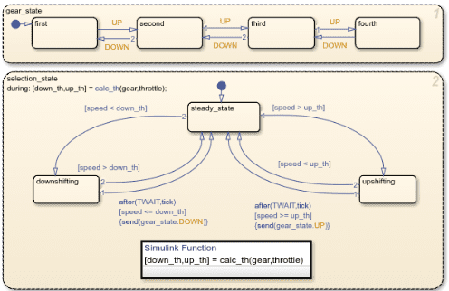
89. How do you model hierarchical state machines in Stateflow?
Ans. Hierarchical state machines are created by nesting states within parent states. This structure improves clarity and scalability. It simplifies complex decision logic.
90. What are junctions and history junctions in Stateflow, and when do you use them?
Ans. Junctions implement conditional branching logic. History junctions remember the previously active state. They are used for complex transition management.
91. How do you perform requirement traceability in Simulink?
Ans. Requirements are linked to model components and test cases. Traceability ensures each requirement is verified. Reports provide audit-ready documentation.
92. What are the key considerations when developing battery management systems (BMS) in Simulink for electric vehicles?
Ans. Accurate SOC and SOH estimation is critical for safety and performance. Thermal management and fault handling are essential. The system must comply with automotive safety standards.
93. How do you handle multi-domain physical systems in Simulink using Simscape?
Ans. Simscape allows integration of multiple physical domains in one model. Energy conservation ensures consistency. This supports realistic system-level simulation.
94. Describe the process of using system identification techniques to develop plant models from experimental data in Simulink.
Ans. Experimental data is collected and preprocessed. Identification algorithms estimate system dynamics. The model is validated against independent data sets.
95. How do you perform co-simulation with Simulink and other simulation tools or environments (e.g., FMI, ROS)?
Ans. Co-simulation uses standardized interfaces like FMI. Data is exchanged during simulation steps. Synchronization ensures consistent system behavior.
96. How do you implement fault detection and diagnostics using Stateflow within a Simulink model?
Ans. Fault conditions are modeled as dedicated states. Transitions detect abnormal behavior. Diagnostic outputs trigger mitigation actions.
97. What are the considerations for ensuring deterministic behavior in Stateflow charts?
Ans. Execution order must be explicitly defined. Ambiguous transitions are avoided. Fixed-step solvers ensure predictable execution.
98. How do you integrate Simulink models into a continuous integration (CI) and continuous deployment (CD) pipeline?
Ans. Automated tests run on each code change. Code generation and coverage checks are included. CI tools ensure consistent validation.
99. What are the best practices for integrating C/C++ code with Simulink models using S-Functions?
Ans. Interfaces must be clearly defined and documented. Memory and data types must be handled carefully. Code should support simulation and code generation.
100. Explain the process of developing a custom GUI in MATLAB for interacting with a Simulink model.
Ans. A custom GUI is developed using MATLAB App Designer. GUI controls interact with the model using callbacks. Parameters and simulations are managed using set_param and get_param.
This was about “Top 100 Model-Based Development Using MATLAB Simulink Interview Questions“. I hope this article may help you all a lot. Thank you for reading
Also, read:
- “Mother of All Deals”: How The EU–India Free Trade Agreement Can Reshape India’s Economic Future
- 10 Free ADAS Projects With Source Code And Documentation – Learn & Build Today
- 10 Tips To Maintain Battery For Long Life, Battery Maintainance
- 10 Tips To Save Electricity Bills, Save Money By Saving Electricity
- 100 (AI) Artificial Intelligence Applications In The Automotive Industry
- 100 + Electrical Engineering Projects For Students, Engineers
- 100+ C Programming Projects With Source Code, Coding Projects Ideas
- 100+ Indian Startups & What They Are Building