Single Pair Ethernet:
how one twisted pair carries it all
A complete, plain-language tutorial on how Single Pair Ethernet moves data — and power — across a single copper pair, from the moment a sensor generates bits to the moment a controller reads them. Every stage is illustrated.
What Single Pair Ethernet actually is
Ordinary Ethernet has always been a bundle of copper. Single Pair Ethernet strips that bundle down to two wires — and in doing so, opens Ethernet to places it could never fit before.
Single Pair Ethernet (SPE) is a family of Ethernet physical-layer standards that send full-duplex data over a single pair of copper conductors — just two wires twisted together — instead of the two or four pairs (four or eight wires) used by the familiar RJ45 cabling in offices and homes. It is standardized by the IEEE under the 802.3 umbrella, the same body that has defined Ethernet since 1983, so an SPE link is not a proprietary bus or a look-alike protocol. It is real Ethernet, carrying real Ethernet frames, all the way up the stack. The only radical change lives at the bottom: the wire.
That single change turns out to matter enormously. A traditional Cat 5e/Cat 6 cable is thick, heavy, and terminated with a bulky eight-position connector. Multiply that across a modern car — which may contain more than a hundred sensors, cameras, radars, and control units — and the wiring harness becomes one of the heaviest and most expensive assemblies in the whole vehicle. By collapsing each link down to two wires, SPE cuts cable weight and diameter dramatically, shrinks the connectors, and still delivers standards-based Ethernet from end to end. The same logic applies on a factory floor, where thousands of sensors need a common, routable network rather than a patchwork of incompatible fieldbuses.
SPE is standards-compliant Ethernet re-engineered to run over two wires, full-duplex, often carrying power on the same pair — built for cars, machines, and sensors where space, weight, and cost rule everything.
It is worth pausing on why SPE arrived when it did. Ethernet spent its first three decades getting faster and cheaper for offices and data centres, but it stayed physically bulky, and it assumed a benign, climate-controlled environment. Meanwhile two industries were straining against the limits of their older networks. Car makers had watched in-vehicle electronics multiply until legacy buses like CAN, LIN, MOST, and FlexRay could no longer keep pace with the bandwidth appetite of cameras and radar, and the tangle of incompatible protocols made software increasingly painful to maintain. Factories, for their part, ran a bewildering assortment of fieldbuses that could not easily talk to the IT systems above them. Both wanted the bandwidth, routability, and universal tooling of Ethernet — but in a form small, light, rugged, and cheap enough to reach every last sensor. SPE is the IEEE’s answer to exactly that demand, developed through a series of 802.3 task forces across the 2010s, and it is why the technology feels purpose-built rather than merely scaled-down: it was designed from the outset for the automotive harness and the factory floor.
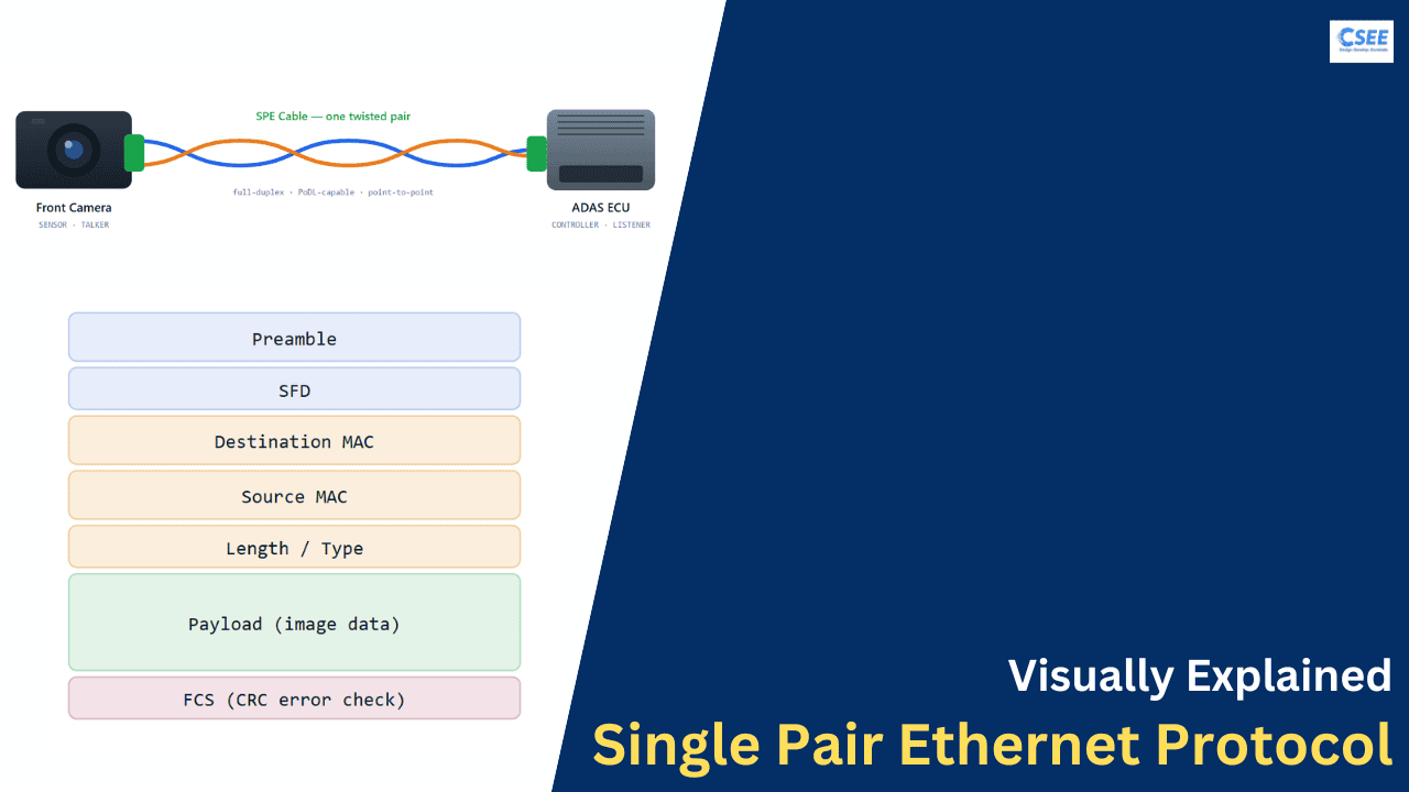
Throughout this tutorial we will follow one concrete example, the same scenario shown in many SPE explainers: a front-facing camera in a vehicle (the sensor, or talker) sending image data to an ADAS ECU — the Advanced Driver Assistance System electronic control unit (the controller, or listener). ADAS is the collection of features like automatic emergency braking, lane-keeping, and adaptive cruise control, and it is hungry for camera and radar data delivered reliably and on time. Watching a single frame of image data travel from the camera’s sensor to the ECU’s processor lets us see every layer of SPE do its job. Let’s start with the map of the whole link.
Notice what is not in that picture: no hub, no switch in the middle, no bundle of eight wires. In its most common automotive form, SPE is a point-to-point link — one device on each end — although a special multidrop variant lets several devices share one pair, which we’ll meet shortly. The green blocks at each end represent the connectors; the two coloured strands are the twisted pair itself, drawn as blue (Wire A) and orange (Wire B) so we can track them through every diagram in this tutorial.
One idea, several standards
“Single Pair Ethernet” is an umbrella. Underneath it sit several IEEE 802.3 variants, each tuned for a different trade-off between speed and distance. Choosing the right one is the first engineering decision on any SPE project.
All SPE variants share the “-T1” suffix, where T means twisted-pair copper and 1 means a single pair. The number in front is the data rate, and the letter after tells you the intended reach or topology. Reading the names this way makes the whole family instantly legible: 100BASE-T1 is 100 Mb/s over one pair; 10BASE-T1L is 10 Mb/s over one pair, long reach.
| Standard | Data rate | Reach | Topology | Typical home |
|---|---|---|---|---|
| 10BASE-T1S | 10 Mb/s | ~15–25 m | Multidrop & point-to-point | In-vehicle edge, replacing CAN/LIN |
| 10BASE-T1L | 10 Mb/s | up to ~1000 m | Point-to-point | Process plants, field instruments |
| 100BASE-T1 | 100 Mb/s | ~15–40 m | Point-to-point | Automotive cameras, sensors |
| 1000BASE-T1 | 1 Gb/s | ~15–40 m | Point-to-point | Automotive backbone, radar/lidar |
| 2.5/5/10GBASE-T1 | 2.5–10 Gb/s | ~15 m | Point-to-point | Autonomous-driving data fusion |
Two of these deserve special attention because they show the range of what “single pair” can mean.
10BASE-T1S — the multidrop rebel
Most Ethernet, including most of SPE, is strictly point-to-point: exactly two devices per link. 10BASE-T1S breaks that rule. Its “S” stands for short reach, and it supports a multidrop topology in which many nodes — a dozen or more — tap onto the same single pair, sharing it like beads on a string. This is a deliberate echo of older automotive buses such as CAN and LIN, which car makers have used for decades precisely because one shared wire can serve a whole cluster of simple devices. 10BASE-T1S lets engineers keep that cheap, shared-wire simplicity while gaining a full Ethernet stack: standard frames, standard addressing, and a clean path to the rest of the network.
10BASE-T1L — the long-distance runner
10BASE-T1L (“L” for long reach) sacrifices speed for distance. At just 10 Mb/s it can reach up to a kilometre over a single pair, and it is designed to operate at very low power, which makes it a natural fit for the process-automation world of refineries, chemical plants, and water treatment. There it is the physical layer beneath Ethernet-APL (Advanced Physical Layer), a specification that adds intrinsic-safety features so the link can run into hazardous, potentially explosive zones without igniting anything. A field instrument a few hundred metres out in a plant can now speak native Ethernet back to the control room over the same two wires that also power it.
Go faster and you must stay shorter. Every jump up the speed ladder — 10 to 100 to 1000 Mb/s and beyond — trades away cable length, because higher-frequency signals attenuate and distort more quickly over copper. SPE gives you a whole spectrum of speed-vs-reach points to pick from.
How two wires stay reliable
Sending data on one pair sounds fragile — a single pair in a car surrounded by motors, ignition sparks, and switching power supplies. Three physical tricks make it not just possible but robust: differential signalling, twisting, and clever line coding.
Differential signalling: the data is the difference
The most important idea in all of SPE is differential signalling. Instead of measuring the voltage on one wire against a shared ground — the way a simple single-ended signal works — the receiver measures the difference in voltage between the two wires of the pair. Wire A and Wire B always swing in opposite directions: when A goes up, B goes down, and vice versa. The transmitted symbol is encoded in that gap between them, not in either wire’s absolute level.
Why go to this trouble? Because it makes the link almost immune to the electrical noise that fills a vehicle or a factory. Noise — a spike from a nearby motor, interference from a power cable running alongside — tends to couple onto both wires of a closely spaced pair almost equally. This shared, unwanted signal is called common-mode noise. When the receiver subtracts one wire from the other to recover the data, the common-mode noise, being nearly identical on both wires, cancels itself out. The useful differential signal survives; the noise largely vanishes. This subtraction is the quiet hero of the entire system.
Twisting: why the pair is a pair
Differential signalling only rejects noise well if the noise really does hit both wires equally — and that is exactly what the twist guarantees. By spiralling the two conductors around each other along the cable, every small segment of Wire A sits, on average, in the same electromagnetic position as the corresponding segment of Wire B. Any external field therefore induces almost the same voltage in both. The twist also cancels the pair’s own outgoing emissions, because the loop area that would radiate keeps flipping direction, so the fields from successive twists cancel in the far field. Twisting is thus a two-way shield: it keeps outside noise from getting in unevenly, and it keeps the pair’s own signal from leaking out to bother its neighbours. The twist rate — how many twists per metre — is a carefully specified cable parameter, not a manufacturing accident.
Line coding & modulation: fitting more into less
The third trick lives in how bits become voltages. A naive scheme would send one bit per voltage transition, but that wastes the wire’s capacity and creates a signal with a strong DC component that is hard to couple through the transformers used for isolation and power injection. SPE PHYs instead use multi-level line coding, most commonly a scheme called PAM3 — Pulse Amplitude Modulation with three levels (−1, 0, +1). By allowing three amplitude levels rather than two, each transmitted symbol can carry more than a single bit’s worth of information, so the wire can run at a lower symbol rate for a given data rate. Lower symbol rate means lower frequency content, which means the signal survives longer over copper and radiates less. Higher-speed SPE variants use even richer schemes (such as PAM4 and beyond) plus forward error correction to push the same principle further.
Two more jobs fall to line coding. First, DC balance: the coding is arranged so that, on average, the signal spends equal time positive and negative, leaving no net DC offset. This lets the link be transformer-coupled — essential for injecting power and for isolation — because transformers cannot pass DC. Second, clock recovery: the receiver has no separate clock wire, so it must extract timing from the data stream itself. The coding guarantees frequent transitions so the receiver’s clock-recovery circuit always has edges to lock onto and never drifts out of sync during a long run of identical bits.
Differential signalling rejects noise by reading the difference. Twisting makes noise hit both wires equally so that rejection works. Line coding packs bits efficiently, balances DC, and hides a clock inside the data. Together they make two wires behave like a dependable digital highway.
How data is sent, step by step
Now the payoff. We follow one frame of camera image data from the moment it is born as bits inside the camera, across the pair, and up into the ADAS ECU’s processor. Ten stages, five on each side, each illustrated.
It helps to keep two layers in mind as we go. The MAC layer (Media Access Control) is the part of Ethernet that deals with frames — addressing, structure, and error checking. The PHY layer (physical layer) is the part that deals with the wire — turning bits into voltages and back. Every SPE device has both, usually as a MAC block inside a microcontroller or SoC talking to a dedicated PHY chip. Our journey walks down the transmitter’s stack (MAC then PHY), across the wire, and back up the receiver’s stack (PHY then MAC).
Transmit side — the camera speaks
Data is generated
The camera’s image sensor captures a frame and its processor converts it into digital data — a stream of binary 1s and 0s. At this point the information is pure application data with no networking wrapper around it at all: just the raw pixels of an image, serialised into bits, waiting to be handed to the Ethernet MAC.
Data framing (MAC layer)
The Ethernet MAC wraps the raw bits into a proper Ethernet frame. It prepends a preamble and start-of-frame delimiter (a fixed pattern that lets the receiver find the frame’s edge and sync its clock), the destination MAC address (who the frame is for — the ECU), the source MAC address (who sent it — the camera), and a length/type field. The image data becomes the payload. Finally the MAC computes a Frame Check Sequence (FCS) — a CRC checksum over the whole frame — and appends it, so the receiver can later verify nothing was corrupted in transit.
Encode (PHY layer)
The framed bits pass from the MAC to the PHY, which prepares them for the wire. The PHY scrambles the bit stream (to avoid long repeating patterns that would concentrate energy at one frequency), maps groups of bits onto symbols, and adds any error-correction coding the standard calls for. The output is no longer thought of as bits but as a sequence of symbols chosen from the coding alphabet — the intermediate form that will become voltage levels in the next stage.
Modulation & line coding
Each symbol is now turned into an actual differential voltage to place on the pair. A symbol of +1 might drive Wire A high and Wire B low; a symbol of −1 does the reverse; a 0 holds them level. The transmitter shapes these transitions carefully so the resulting waveform stays within the spectral mask the standard defines — keeping energy in the intended band, minimising emissions, and preserving DC balance so the signal can pass through coupling transformers.
Transmit on the single pair
The differential signal is driven onto the one twisted pair and travels toward the ECU. Crucially, because SPE is full-duplex, the camera is transmitting on the very same pair over which the ECU may simultaneously be sending data the other way. And if PoDL is in use, a DC power feed rides along the same wires at the same time. One pair, doing three jobs at once: outbound data, inbound data, and power.
Receive side — the ECU listens
Receive the signal
The differential signal arrives — attenuated, smeared by the cable, and mixed with noise and (in full-duplex) the ECU’s own outgoing transmission. The ECU’s PHY front end senses the voltage difference between Wire A and Wire B, applies an equaliser that reverses the cable’s distortion, and recovers the timing clock from the transitions in the stream. What comes out is a usable but still messy analog waveform that needs cleaning before it can be read.
Echo cancellation
This is the cleverest step, and the one that makes single-pair full-duplex possible. Because both devices send at once on one pair, each receiver hears a strong reflection of its own transmitter — an echo. Fortunately, the ECU knows exactly what it just sent. Its PHY keeps a model of the echo, generated from its own outgoing signal, and subtracts that model from what it hears. What remains is the actual incoming signal from the camera, now separated from the ECU’s own noise. Adaptive filters continuously tune the echo model as cable conditions change.
Decode
With a clean signal in hand, the PHY reverses the encoding. It slices the recovered waveform at the symbol clock, decides which symbol each interval represents (−1, 0, or +1), applies any forward-error-correction to fix residual bit errors, de-scrambles the stream, and maps the symbols back into the original bits. The physical layer’s work is essentially done: it has turned voltages back into the exact bit sequence the transmitter’s PHY produced.
Deframe (MAC layer)
The bits flow up to the ECU’s MAC, which reverses the framing of step 2. It locks onto the preamble and SFD, reads the destination address to confirm the frame is meant for it, and — critically — recomputes the CRC over the received frame and compares it against the transmitted FCS. If they match, the frame is intact; if not, it is discarded as corrupted. Assuming the check passes, the MAC strips off all the headers and the FCS, leaving just the original payload.
Data delivered
The recovered payload — the very same image bits the camera produced back in step 1 — is handed to the ECU’s application or processor. The ADAS software can now run its object-detection and lane-tracking algorithms on a frame that has crossed a single pair of wires and arrived bit-for-bit identical. One complete data transfer is done, and the whole cycle repeats thousands of times a second for every frame the camera captures.
Generate → frame → encode → modulate → transmit → receive → cancel echo → decode → deframe → deliver. The transmitter walks down its stack (MAC to PHY to wire); the receiver walks up its stack (wire to PHY to MAC). Everything above the PHY is ordinary Ethernet — which is exactly why SPE slots so cleanly into existing networks.
Full-duplex on one pair
The single most counter-intuitive thing about SPE is that both devices talk and listen simultaneously over the same two wires. Understanding how deserves its own section.
In older half-duplex links, a shared medium can only carry traffic in one direction at a time, so devices take turns and collisions must be managed. SPE instead runs full-duplex: the camera and the ECU each transmit continuously, in both directions, on the same pair, with no turn-taking. The two signals literally superimpose on the wire — the voltage at any instant is the sum of what both ends are driving. That sounds like a recipe for chaos, and it would be, were it not for the echo cancellation we met in step 7.
The key insight is that each device knows precisely what it is transmitting, so it can predict and remove its own contribution from the combined signal on the wire. After a receiver subtracts a faithful model of its own outgoing signal (its echo), what is left must be the signal from the other end. Both directions can therefore coexist on one pair, each recoverable, with the transceivers’ digital signal processing doing the separation continuously and adaptively. This is why the PHY in an SPE device is far more sophisticated than a simple line driver: it is a small, specialised signal-processing engine.
Timing and determinism: why full-duplex matters for safety
Full-duplex is not only about throughput; it is also about determinism. In a safety system like ADAS, it is not enough for a camera frame to arrive — it must arrive on time, every time, with a bounded, predictable delay. Half-duplex media introduce uncertainty because a device may have to wait for the wire to clear before it can transmit, and contention makes worst-case latency hard to guarantee. By letting both ends transmit whenever they need to, full-duplex removes that waiting entirely: there is no queue for access to the medium, so the latency of a link becomes stable and calculable.
On top of this, SPE links commonly carry Time-Sensitive Networking (TSN), a set of IEEE standards layered above the physical link that adds precise time synchronisation and traffic scheduling across a whole network. TSN lets a designer reserve bandwidth for critical streams, prioritise a braking command over a comfort feature, and keep every node’s clock aligned to within microseconds. Combined with SPE’s deterministic full-duplex links, TSN is what turns a collection of two-wire connections into a network you can actually trust with a moving vehicle or a running machine. This is a crucial reason the automotive and industrial worlds chose Ethernet as their converged network rather than inventing yet another proprietary bus: the timing guarantees they need already existed as open standards, waiting to run over a suitably small physical layer.
The key enablers, gathered in one place
Six technologies, working together, are what let two wires behave so well. We have met them all; here they are as a checklist.
- Differential signalling — data lives in the voltage difference between the two wires, giving strong immunity to common-mode noise.
- Echo cancellation — each PHY subtracts its own transmission, removing self-interference and enabling full-duplex on one pair.
- Advanced PHY / DSP — equalisation, adaptive filtering, timing recovery, and error correction reverse the cable’s distortion.
- Line coding — multi-level schemes (PAM3/PAM4) ensure DC balance and reliable clock recovery while packing bits efficiently.
- Shielding & twisting — the twist balances noise coupling; optional shielding blocks EMI and crosstalk in harsh settings.
- PoDL — power and data share the same pair, so many devices need no separate power cable at all.
PoDL: power over the data line
If SPE only saved wires by carrying data, it would already be worthwhile. But it can also carry power on the same pair — halving the wire count again for many devices.
Power over Data Line (PoDL) is the single-pair cousin of the familiar Power over Ethernet (PoE) used to run phones and cameras over office cabling. The principle is the same: inject a DC voltage onto the wires that already carry data, and separate the two at each end. The trick is frequency. Data is a high-frequency alternating signal; power is DC (zero frequency). A small network of inductors (which pass DC but block high-frequency signal) and capacitors (which pass signal but block DC) at each end cleanly splits the combined feed back into a data path and a power path. The data transceiver never sees the DC; the power circuitry never sees the data.
For a car with dozens of small sensors, or a plant with hundreds of field instruments, this is transformative. A camera at the corner of a bumper, or a temperature transmitter far out in a process unit, needs only a single two-wire cable for everything: it draws its operating power and exchanges its data over the identical pair. No separate power run, no local supply, fewer connectors, less to go wrong. PoDL is defined across a range of power classes so designers can match voltage and current to what each endpoint needs.
Applications of Single Pair Ethernet
SPE was born from two pressures at once: cars needing to network an explosion of sensors, and factories wanting to retire a zoo of incompatible fieldbuses. From those two roots it has spread into rail, energy, buildings, medical devices, and beyond — anywhere thin, cheap, powered, standards-based wiring matters.
The reason SPE reaches so many industries is that it solves one very general problem: how to bring real, routable Ethernet — the same protocol that runs the internet — all the way down to the smallest, most numerous, most cost-sensitive devices in a system, without a heavy cable or a second power run. Wherever a designer is currently forced to choose between a capable-but-bulky network and a cheap-but-limited fieldbus, SPE offers a third option that is both. The map below shows how one vehicle might use several SPE variants at once, and the sections that follow walk through the major domains.
Automotive — the founding use case
SPE was, in effect, invented for the car. A modern vehicle carries dozens of cameras, radar and ultrasonic sensors, and increasingly lidar, all feeding ADAS and autonomous-driving controllers that must fuse them in real time. 100BASE-T1 and 1000BASE-T1 carry that sensor data with the bandwidth and low, deterministic latency those safety functions demand, while cutting the wiring harness — one of a car’s heaviest and costliest assemblies — down dramatically. At the simpler edge, 10BASE-T1S multidrop brings Ethernet to things that once needed CAN or LIN: door modules, seat controls, ambient lighting, and body sensors, several sharing a single pair. The payoff is a single, converged, IP-based in-vehicle network from the smallest switch to the central compute, which is far easier to secure, update, and diagnose than the old patchwork of separate buses.
Industrial automation & process control
On the factory floor and in process plants, SPE’s mission is convergence: replacing a tangle of legacy fieldbuses with one routable Ethernet network that runs unbroken from the control room down to the last sensor. 10BASE-T1L, with its kilometre reach and low power, is the physical layer beneath Ethernet-APL, which adds intrinsic-safety features so a link can run into hazardous, potentially explosive zones — refineries, chemical and oil-and-gas plants — without becoming an ignition source. A field transmitter hundreds of metres out can now speak native Ethernet back to the plant, powered over the very same pair. That end-to-end IP continuity is exactly what “Industry 4.0” and the Industrial IoT need: data that flows from a valve or a flow meter straight up to analytics and the cloud without protocol gateways in the way.
Buildings, infrastructure & IoT
Buildings are dense with small networked devices — HVAC controllers, lighting, occupancy and air-quality sensors, access-control readers, and cameras — and each has traditionally meant its own cabling and often its own control protocol. SPE lets all of them ride thin, inexpensive two-wire runs that also deliver power via PoDL, so a sensor or a light needs a single cable for everything. Because it is standard Ethernet, building automation can finally scale to thousands of nodes on one coherent IP network rather than isolated islands of proprietary wiring, simplifying installation, commissioning, and long-term management.
Rail, energy & transportation
Trains and trackside systems face the same weight, length, and harsh-environment pressures as cars, but over far greater distances — which suits SPE’s long-reach variants well. Onboard, SPE thins the cabling for passenger-information displays, door and brake sensors, and surveillance; trackside, its reach and PoDL support distributed signalling and monitoring equipment. In the energy sector, substations and renewable installations use SPE to bring communications and power to widely spaced sensors and protection devices over a single robust pair.
Medical, robotics & other frontiers
Any system that packs many sensors into a tight, weight-conscious enclosure is a candidate. In medical devices — imaging systems, patient monitors, surgical robots — SPE reduces cable bulk inside instruments while keeping a clean, standards-based data path. In robotics and drones, every gram and every millimetre of cable in a moving joint or airframe counts, so a two-wire link that also carries power is highly attractive. The same reasoning is drawing SPE into agriculture, aerospace, and smart-city infrastructure, wherever dense sensing meets tight space and cost budgets.
Everywhere SPE wins, the same three constraints dominate: space, weight, and cost. Wherever those rule and you still want the reach and interoperability of real Ethernet — with power thrown in on the same pair — a single pair is the answer.
SPE vs traditional Ethernet
SPE does not replace the four-pair Ethernet in your office wall. It extends Ethernet’s reach into a different set of problems. Here is how the two compare.
| Property | Traditional Ethernet (e.g. 1000BASE-T) | Single Pair Ethernet |
|---|---|---|
| Conductors | 4 pairs (8 wires) | 1 pair (2 wires) |
| Connector | RJ45, bulky | Compact SPE (IEC 63171 family) |
| Cable weight & size | Thick, heavy | Thin, light |
| Reach | ~100 m | 15 m up to ~1000 m (variant-dependent) |
| Power delivery | PoE | PoDL (over the single pair) |
| Topology | Point-to-point (via switches) | Point-to-point; also multidrop (10BASE-T1S) |
| Primary home | Offices, data centres, homes | Vehicles, factories, field devices, IoT |
| Upper layers | Standard Ethernet / IP | Identical — same frames, same IP stack |
The last row is the most important. Because SPE keeps everything above the physical layer unchanged, an SPE device and a conventional Ethernet device speak the same language once their frames meet a switch that bridges the two media. SPE is not a walled garden; it is Ethernet’s on-ramp for the smallest, most constrained corners of a network.
Connectors and cabling
A quiet but essential piece of the SPE story is standardised hardware. The IEC 63171 family defines compact SPE connectors — far smaller than RJ45 — so the wiring savings at the cable translate into savings at every mating point too. Cabling is likewise specified for consistent impedance, twist rate, and shielding options (unshielded UTP for benign environments, shielded STP where EMI is severe), because the PHY’s careful signal processing assumes a cable with predictable electrical behaviour. Standardised connectors and cable also mean multi-vendor interoperability: parts from different suppliers mate and perform to the same spec.
Advantages and challenges
SPE is a strong fit for many jobs and a poor fit for a few. Knowing both sides is what makes an engineer, rather than an enthusiast.
What SPE gives you
Less wire, weight, and cost — two conductors instead of eight, with matching small connectors. Power and data on one pair via PoDL. Real Ethernet end to end, so the same IP tools, diagnostics, and security apply from cloud to sensor. Long reach options up to a kilometre. Multidrop where a shared bus makes sense. Scalable speed, from 10 Mb/s to 10 Gb/s, on the same basic medium.
What to watch for
Speed trades against distance — you cannot have both maximum rate and maximum reach. Sophisticated PHYs — the DSP that makes one pair reliable adds silicon complexity and cost per node. Cable discipline — twist rate, impedance, and shielding must meet spec or performance degrades. Ecosystem maturity — younger than RJ45 Ethernet, so tooling, connectors, and installer familiarity are still growing, though quickly.
One data transfer, remembered
If you take one thing from this tutorial, let it be the journey of a single frame. Here is the whole cycle in nine beats.
Transmit side
1. Camera generates the image data as bits.
2. MAC frames the data (headers + FCS).
3. PHY encodes bits into symbols.
4. PHY modulates symbols to a differential signal.
5. The signal travels over the single twisted pair.
Receive side
6. ECU PHY receives and equalises the waveform.
7. Echo canceller removes the ECU’s own signal.
8. PHY decodes symbols back into bits.
9. MAC checks the FCS and extracts the payload.
→ Data delivered to the ADAS application. ✓
Single Pair Ethernet takes standards-based Ethernet, engineers its physical layer down to two wires, runs it full-duplex with echo cancellation, and — where wanted — carries power on the same pair. That is how data (and power) travel reliably over a single twisted pair.