Hello guys, Welcome back to our blog. Here in this article, we will discuss what is ADC, the working of ADC (or analog to digital converter), features of ADC, inverter questions on ADC, and its applications.
If you have any electrical, electronics, and computer science doubts, then ask questions. You can also catch me on Instagram – CS Electrical & Electronics.
Also, read:
- CAN Protocol Tutorial, Working, Frames, Interview Q’s, Errors
- Top 16 Robots That Will Change The World, Humanoid Robots
- What Are Parasitic Capacitance And Inductance, Causes, Avoid
Analog To Digital converter (ADC)
Almost all environmental variables that can be measured are analogs, such as temperature, sound, pressure, and light. Consider a temperature monitoring system where digital computers and processors are unable to acquire, analyze, and interpret temperature data from sensors. Therefore, in order for this system to connect with digital processors like microcontrollers and microprocessors, an intermediary device is required to transform the analog temperature data into digital data.
An electrical integrated circuit known as an analog-to-digital converter (ADC) is used to convert analog signals, such as voltages, to digital or binary form, which is made up of 1s and 0s. The majority of ADCs accept voltage inputs of 0 to 10V, -5V to +5V, etc., and provide digital output in the form of a binary integer in response.
An electronic device known as an analog-to-digital converter (ADC) transforms continuous time-varying analog signals into discrete-time digital signals so they can be easily read by digital devices.
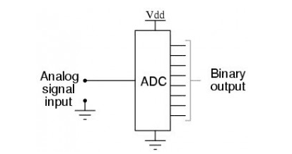
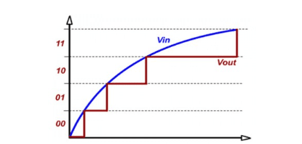
It can be used in a variety of electronic tasks. In control systems, data computing, data transfer, and information processing, ADC transform the physical quantities of a real-world occurrence into a digital language. The ADC’s input/output relationship is depicted in the image below.

Features Of ADC / Analog To Digital Converter
There are various methods for converting an analog signal to a digital one. ADC08xx series and other ADC chip varieties are offered on the market by various vendors. Therefore, using discrete components allows for the design of a straightforward ADC.
Sample rate and bit resolution are the two main characteristics of an ADC.
The speed at which an ADC can convert an analog signal to a digital signal is known as its sample rate. The accuracy with which an analog-to-digital converter can transform the signal from analog to digital is known as bit resolution.
The high data collection rate of an ADC converter, even with multiplexed inputs, is one of its main advantages. The development of numerous ADC integrated circuits (ICs) has increased the accuracy and speed of data acquisition from diverse sensors. Improved measurement repeatability, low power consumption, precise throughput, high linearity, good Signal-to-Noise Ratio (SNR), and other dynamic properties characterize high-performance ADCs.
Measurement and control systems, industrial instruments, communication systems, and all other sensory-based systems are only a few examples of ADCs’ numerous uses. ADCs are categorized according to their performance, bit rates, power consumption, cost, etc.
Working Of ADC / Analog To Digital Converter

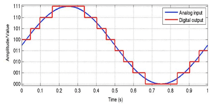
Analog signals are those that have a continuous sequence and continuous values in the real world (there are some cases where it can be finite). These signals can be produced by sound, light, temperature, and movement. The discrete values that make up a digital signal’s representation are broken down into sequences based on the time series or sampling rate (more on this later). The best way to do this is with a picture, obviously! An excellent illustration of how analog and digital signals look is shown in the below figure.
Values must be digital data in order for microcontrollers to read them. This is because, depending on the resolution of the ADC and the system voltage, microcontrollers can only sense “levels” of the voltage.
When converting analog signals to digital signals, ADCs follow a sequence. To read the digital signal, they first sample the signal, quantify it to ascertain its resolution, set binary values on it, and send it to the system. The sample rate and resolution of the ADC are two crucial features.
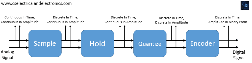
Following is a block diagram of an ADC that contains a sample, hold, quantize, and encoder. The following are several ways to carry out the ADC process.
The analog signal is first applied to the first block, which is a sample, wherever a precise sampling frequency can be achieved. Within the second block, similar to Hold, the sample’s amplitude value can be held as well as maintained. Through the third block like quantizing, the held sample can be quantized into a discrete value. A binary number is created from the discrete amplitude by the final block-style encoder.
The block diagram above can be used to show how analog-to-digital signal conversion works in ADC.
01. Sample: The analog signal can be sampled at a precise interval of time in the sample block. Although the samples are discrete with respect to time, they are employed in continuous amplitude and have real value. The sampling frequency is crucial for converting the signal. Consequently, a precise rate can be maintained. The sample rate can be fixed based on the needs of the system.
02. Hold: In an ADC, the HOLD block is the second block and serves no purpose other than to hold the sample amplitude until the next sample is obtained. Therefore, the hold value doesn’t change until the following sample.
03. Quantize: This third block in an ADC is primarily utilized for quantization. This has the primary purpose of changing the amplitude from continuous (analog) to discrete. The hold block’s continuous amplitude value transitions into discrete amplitude during the quantized block. Since the signal now contains discrete amplitude and time information, it will be in digital form.
04. Encoder: An encoder, the last component of the ADC, transforms the signal from digital to binary form. We are aware that binary signals are used to operate digital devices. Therefore, using an encoder, it is necessary to convert the signal from digital to binary. So this is how an ADC converts an analog signal to a digital one. The full conversion can be completed in less than one microsecond.
Sampling Rate & Resolution In ADC
The sampling frequency, or rate of sampling, of an ADC, can be related to its speed. The term “samples per second,” with units in SPS or S/s (or, if you’re using sampling frequency, it would be in Hz), is used to describe the sampling rate. Simply put, this refers to how many samples or data points are collected in a second. The ADC can withstand higher frequencies the more samples it takes.
The following is a crucial equation for the sampling rate:
fs = 1/T
Where,
Sample Rate/Frequency = fs
T = The sample’s duration or the interval between samples.
For instance, it appears that fs is 20 S/s (or 20 Hz) and T is 50 ms in Figure 1. Despite the extremely slow sample rate, the signal nonetheless resembled the analog signal that it was modeled after. This is due to the fact that the original signal’s frequency is a low 1 Hz, suggesting that the frequency rate was still sufficient to recreate a signal with a similar frequency.
You might wonder, “What happens when the sample rate is significantly slower?” The sampling rate of the ADC must be known in order to determine whether it will result in aliasing. A digital image or signal that has been sampled and then reconstructed is said to be aliased if it differs significantly from the sampled original.
The ADC won’t be able to reconstruct the original analog signal if the sampling rate is slow and the signal’s frequency is high, which will lead to inaccurate data being read by the system. The below figure displays a nice instance.
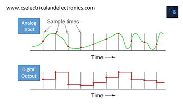
You can see in this example where the sampling takes place in the analog input signal. Because the sampling rate is insufficient to keep up with the analog signal, the output of the digital signal is in no way similar to the original signal. As a result, the analog signal’s complete picture will no longer be seen in the digital system due to aliasing.
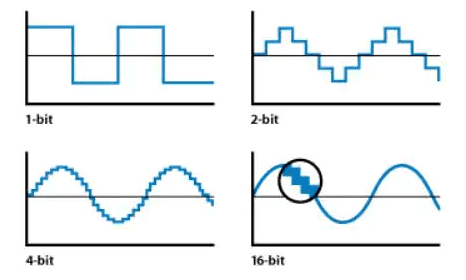
The resolution and precision of the ADC are related. The bit length of the ADC can be used to gauge its resolution. The figure below provides a brief illustration of how it enables the digital signal to produce a more precise signal. Here, you can see that there are just two “levels” in the 1-bit. The levels rise as the bit length is increased, more closely resembling the original analog signal.
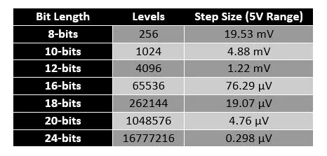
The bit resolution is crucial to know if you require your system to read voltage levels with accuracy. Both the bit length and the reference voltage affect resolution. These equations aid in determining the total resolution of the signal you are attempting to enter in terms of voltage:
ADC Resolution Formula Example
Size of Step = VRef/N
Where,
- Step Size is the voltage resolution of each level.
- The voltage reference is VRef (range of voltages)
- N = Total ADC level size
Use this equation to determine N size:
N = 2n
Where,
- Bit Size = n
Let’s take the case of needing to interpret a sine wave with a voltage range of 5. The bit size of the ADC is twelve bits. Equation 4’s 12 to n input will result in N = 4096. Knowing that and having the voltage reference at 5V gives you: 5V/4096 as the step size. The step size will be roughly 0.00122V, as you will discover (or 1.22mV). This is precisely because the digital system can detect voltage changes with an accuracy of 1.22 mV.
The accuracy would drop to only 1.25V if the ADC had a very short bit length, say only 2 bits. This is quite poor because the system could only be informed of four voltage levels (0V, 1.25V, 2.5V, 3.75V, and 5V).
Working Of 3-Bit ADC
The accuracy of the digital value that captures the original analog signal in ADCs is determined by two variables. These include sampling rate and quantization level, sometimes known as bit rate. The process of converting from analog to digital is shown in the diagram below. The resolution of digital output is determined by the bit rate, as seen in the picture below, where a 3-bit ADC is used to transform the analog signal.
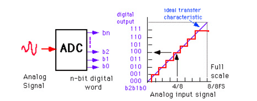
Assume that a one-volt signal needs to be converted to digital using the above-described 3-bit ADC. As a result, there are a total of 23=8 divisions available to provide 1V output. As a minimum change or quantization level, this result of 1/8=0.125V is represented for each division as 000 for 0V, 001 for 0.125V, and similarly up to 111 for 1V.
We will improve the signal’s precision if we increase the bit rates, such as 6, 8, 12, 14, and so on. So, when a change in the digital representation of an analog signal occurs, the bit rate or quantization produces the least output change in the signal’s value.
Types Of ADC / Analog To Digital Converters
01. FLASH ADC
This flash ADC is also called parallel ADC, which is mostly used ADC because of its speed. This flash analog to digital converter consists of the comparators connected in series which measure and compares the input voltages. It consists of a priority encoder that will provide the required efficient binary data. This ADC is highly expensive and it possesses high-speed working characteristics.
02. PIPELINED ADC
The pipelined ADC consists of successive approximation quantizers which will look after the samples generated. The input is ready for execution as it is the pipeline technologies advantage. The coarse conversion is an important step in the pipelined ADC.
03. SUCCESSIVE APPROXIMATION ADC
The SAR ADC is a modest technology of the ADC. It uses digital logic which will provide us with the closest value to the analog value. The circuit of the SAR ADC mainly consists of the comparators, output latches and the successive approximation register (SAR), and the D/A converter. The SAR is used to clear the MSB value of the input signal if the comparator output is low compared to the value. The SAR plays a key role in the fast and efficient conversion of the analog to the digital state.
04. SIGMA-DELTA ADC
The sigma-delta converters are also called oversampling converters. It consists of mainly two blocks sigma-delta modulator and the digital filter. The sigma-delta modulator is made up of the integrator and the comparator in addition to single-bit DAC. The digital filter acts as the binary data converter. It consists of the priority encoder which will convert the digital value to binary data which is taken as input to the digital devices.
The above-mentioned are the most used analog to digital-converters in the real world. Now let us go with the advantages and the disadvantages of the Analog to Digital Converter.
Advantages Of ADC / Analog To Digital Converter
- The pipelined analog to digital converters provides high resolution at high speed.
- Flash A/D are the fastest converters compared to all the converters.
- Successive approximation converters are more reliable and operate as HIGH-speed ADC.
- Sigma-delta A/D converters provide high resolution compared to all the converters.
Disadvantages Of ADC / Analog To Digital Converter
- Flash A/D converters are highly expensive.
- The circuit will become complex as the comparators in the circuit increase.
- The working of the successive approximation ADC will be very slow under high resolution.
- Pipeline A/D converters are very sensitive to the PCB layout.
- The conversion process becomes comparatively difficult in the pipeline ADCs as the non-periodic rate will be comparatively high.
Applications Of ADC / Analog To Digital Converter
- ADCs are used in Audio and video devices.
- Digital multimeters and PLCs are equipped with ADCs.
- They are used in mobile phones.
- They are used for analog medical image processing and also in medical instrumentation.
- They are used in oscilloscopes and RADAR processing.
ADC Interview Question
01. What is the main function of ADC?
Ans. An analog signal, such as voltage, is converted to a digital form by an analog-to-digital converter (ADC) so that a microcontroller can read and process it. ADC converters are now found inside the majority of microcontrollers. Any type of microcontroller can also be connected to an external ADC converter.
02. How is ADC resolution calculated?
Ans. It is stated as the number of bits the ADC outputs. As a result, an ADC that transforms an analog signal into a 12-bit digital value has a 12-bit resolution. -1. The resolution with a 3.3 V reference voltage is 3.3/212 = 3.3/4096 = 0.805. (mV).
03. Which type of logic is used in ADC?
Ans. Since the SAR ADC uses digital logic to converge the analog input voltage to the nearest value, it is a significantly faster ADC IC than dual slope and flashes ADCs. The sequential approximation register (SAR), output latches, comparator, and D/A converter make up this circuit.
04. Which amplifier is used in ADC?
Ans. The signal can be scaled using an op amp to the ideal amplitude range for the ADC. When driving a high-speed ADC, the CLC5526 variable gain differential amplifier is intended to offer both gain and attenuation.
05. What is 3-bit ADC?
Ans. A 3-bit Flash ADC is made up of a priority encoder, a resistive voltage divider circuit with eight series resistors, and seven comparators. The positive terminal of the comparator is connected to the input analog voltage, and the negative terminal is connected to the reference voltage.
This was about “Analog To Digital converter (ADC)“. I hope this article may help you all a lot. Thank you for reading.
Also, read:
- 10 Free ADAS Projects With Source Code And Documentation – Learn & Build Today
- 100 + Electrical Engineering Projects For Students, Engineers
- 100+ Indian Startups & What They Are Building
- 1000+ Automotive Interview Questions With Answers
- 1000+ Electronics Projects For Engineers, Diploma, MTech Students
- 1000+ MATLAB Simulink Projects For MTech, Engineering Students
- 2026 Hackathons That Can Change Your Tech Career Forever
- 50 Advanced Level Interview Questions On CAPL Scripting