Imagine testing a car’s entire control system — engine management, braking, ADAS — before a single prototype is built. Sounds futuristic?
Well, that’s exactly what engineers do today using MiL, SiL, PiL, HiL, DiL, and ViL testing methods!
Welcome to our deep dive into automotive testing. Today, we’re exploring six crucial stages that ensure vehicles are safe, reliable, and intelligent before hitting the road. By the end, you’ll understand how modern car systems evolve — from virtual models to real-world validation.
🧩 Model-in-the-Loop (MiL)
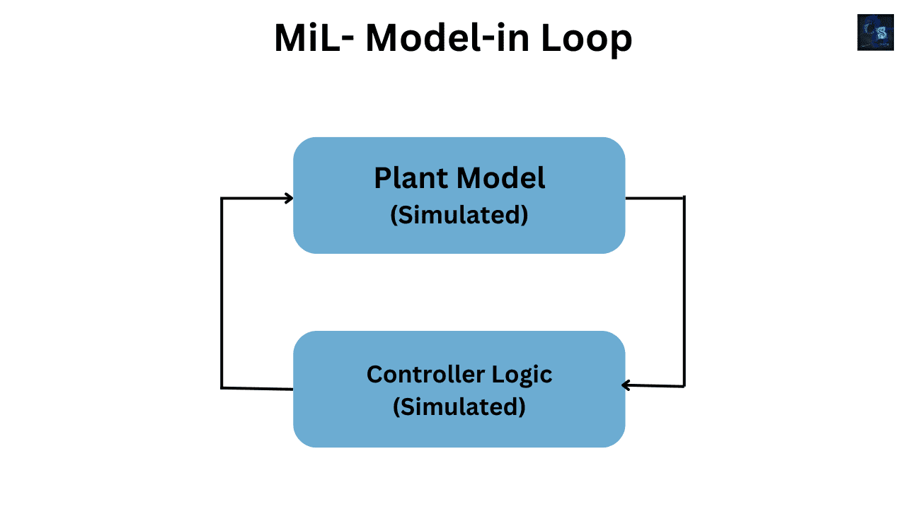
Our first testing stage in the automotive development cycle is Model-in-the-Loop, commonly called MiL. This is where everything begins — the foundation of model-based design. In the MiL stage, both the plant model and the controller model exist purely in the virtual world. The plant model represents the physical system — the vehicle, the engine, the brakes, or whatever mechanical system you are trying to control. It captures the physics, dynamics, and response of that system. Meanwhile, the controller model represents the brain of the system — it contains the algorithms, logic, and decision-making processes that determine how the vehicle behaves under different conditions.
In simpler terms, think of MiL as the playground where engineers can test their ideas safely inside a computer, before touching any hardware. Everything happens in simulation. Tools like MATLAB and Simulink are most commonly used because they allow engineers to visually create mathematical models, simulate their interactions, and analyze behavior in real time. You can think of it as a virtual lab for automotive software design.
At this stage, there’s no need for physical prototypes or real electronic control units (ECUs). The vehicle, its sensors, its actuators, and its controller all live as mathematical models. Engineers can run these models together in a loop — that’s why we call it “Model-in-the-Loop.” The plant model sends simulated signals to the controller, and the controller reacts just like it would in a real car, sending outputs back to the plant. This closed-loop environment allows for very fast testing and iteration cycles.
One of the biggest advantages of MiL is speed and flexibility. You can modify algorithms instantly, re-run tests, and visualize results within seconds. This enables engineers to experiment with new control strategies — for example, tuning a cruise control system, adjusting a braking curve, or testing an electric motor torque control algorithm — all without any risk or cost of damaging physical equipment.
In the MiL phase, engineers often explore “what-if” scenarios — thousands of them. They can simulate how a car would behave if it’s driving uphill, going downhill, facing sudden braking, or driving in icy conditions. They can even inject artificial faults — like sensor noise, delayed signals, or stuck actuators — and analyze how the control algorithm responds. This is incredibly powerful because it allows teams to detect design flaws or edge cases very early, long before physical systems are built.
Let’s take a simple example — the cruise control system. The plant model would represent the car’s longitudinal dynamics: its mass, drag, tire friction, and engine torque response. The controller model would contain the algorithm that decides how much throttle to apply to maintain a desired speed. In MiL, you can run this virtual car in various road conditions — like steep hills, curves, or sudden wind resistance — and see how well the algorithm keeps the speed constant. You can even measure overshoot, settling time, and control effort, just as you would in a real lab.
But MiL isn’t just about testing — it’s also about refinement and validation. It’s at this point that engineers tune control parameters, optimize logic, and ensure that the algorithm performs consistently across different operating conditions. It’s also where they start linking requirements to specific model components — something known as requirement traceability. This ensures that every control function implemented in the model can be traced back to a specific design requirement.
Now, let’s discuss what exactly gets verified in MiL. There are at least ten crucial things engineers look for in this stage:
- Control logic correctness — verifying that the control flow and state transitions behave as intended.
- Algorithm stability — ensuring that feedback loops (like PID controllers or estimators) are mathematically stable.
- Response time to inputs — checking how quickly the system reacts to changes in throttle, brake, or steering.
- Sensor and actuator logic consistency — confirming that the model properly interprets input and output signals.
- Boundary and limit behavior — making sure that outputs stay within defined physical and safety limits.
- Fault and failure handling logic — testing how the controller behaves under abnormal or failure conditions, such as sensor dropout or actuator faults.
- State transitions and timing logic — ensuring that state machines switch correctly between modes like “idle,” “drive,” and “brake.”
- Performance under noise and disturbances — verifying that the system remains stable even when simulated disturbances or random noise are added.
- Requirement traceability — linking every behavior in the model to specific system or customer requirements.
- Early safety and redundancy checks — confirming that safety mechanisms like fallback logic or redundant signals work as intended.
Each of these verification points ensures that the design is not just functional, but also reliable and safe to move forward to the next testing stages. Remember, the cost of fixing a bug found in MiL is far lower than fixing the same issue in HiL or vehicle testing. That’s why companies emphasize this stage so much — it helps reduce downstream costs and shortens development time dramatically.
Another key strength of MiL is its ability to perform automated simulations. Engineers can set up test suites to run thousands of simulations overnight, using different parameter sets and input profiles. The results are automatically logged and compared against expected outputs. If something deviates, the model is flagged for further inspection. This kind of automation brings software-like testing discipline to control system design.
Beyond control algorithms, MiL can also validate fault detection and diagnostic strategies. For example, an engineer might simulate a failed temperature sensor and check if the model triggers a fault code or switches to a backup strategy. Such early testing ensures that diagnostic logic will be robust in the real ECU later.
In modern automotive systems, where electronics and software control nearly every aspect of the vehicle — from braking to stability control to battery management — MiL testing acts as a virtual proving ground. It enables teams to integrate multiple subsystems — like powertrain, suspension, and ADAS — in a single simulation environment. This makes it possible to study interactions between systems long before the physical integration phase.
Another important aspect of MiL is data visualization and analysis. Engineers can plot signals, visualize control surfaces, and even create 3D animations of vehicle motion to intuitively understand how the algorithms are performing. Such visualization not only helps technical teams but also aids communication with non-technical stakeholders, making it easier to demonstrate progress or validate concepts.
As automotive systems grow more complex, MiL has evolved too. Advanced MiL setups may include real-time simulation, Monte Carlo analysis, or even AI-driven test scenario generation, where machine learning algorithms generate new test cases based on coverage gaps. This helps engineers push their models to the limits and uncover issues that might never appear in a simple test run.
At this stage, the goal isn’t just to prove that the model works — it’s to build confidence in the algorithm before moving to the next level of testing, which is Software-in-the-Loop (SiL). In SiL, engineers take the validated control model, generate the corresponding source code, and then run it inside a simulation to ensure the code behaves the same as the model. But before reaching that point, MiL ensures that the control concept itself — the logic, equations, and interactions — are sound.
To summarize, Model-in-the-Loop is the first major step in the model-based design process. It’s where engineers bring ideas to life in a purely digital world, validate them thoroughly, and prepare them for implementation. By using MiL, automotive teams can accelerate innovation, reduce physical testing costs, and ensure that control systems meet performance, safety, and reliability requirements from day one.
So, whether you’re building a simple cruise control system, an electric vehicle’s regenerative braking algorithm, or an autonomous driving function, MiL is where you’ll start your journey. It’s where your concept evolves from equations to a working virtual prototype — the first proof that your design can actually work on the road.
💻 Software-in-the-Loop (SiL)
Now that we’ve built and validated our algorithms in the Model-in-the-Loop stage, the next logical step is to move toward Software-in-the-Loop, or SiL.
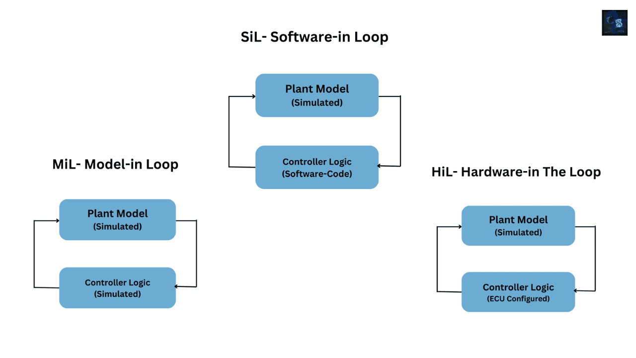
In MiL, everything — both the plant and the controller — existed as simulation models. But in SiL, we take a big leap forward: we replace the controller model with actual software code. The plant, representing the vehicle dynamics, remains simulated, but the controller is now in its executable form — just like it will run inside an Electronic Control Unit (ECU).
You can think of it this way: in MiL, we were testing ideas; in SiL, we’re testing the implementation of those ideas.
During SiL testing, the control logic that was designed using tools like MATLAB/Simulink or Stateflow is converted into source code — usually C or C++ — using tools such as Embedded Coder or TargetLink. This code is then compiled and executed on a PC or virtual platform that mimics the embedded environment. Sometimes, engineers integrate this software back into Simulink using S-functions, allowing it to interact seamlessly with the plant model during simulation.
So, the key difference between MiL and SiL is this:
In MiL, you test algorithms as graphical models.
In SiL, you test the code generated from those models — to ensure that what the code does matches exactly what the model was supposed to do.
This stage acts as a bridge between design and implementation. It gives engineers a chance to detect issues in code behavior early — before ever flashing it to hardware. By running the actual compiled software in a virtual plant environment, developers can verify that the logic hasn’t changed, that the numerical computations are accurate, and that the software structure performs as intended under all conditions.
One of the major goals of SiL is model-code equivalence testing. The code should behave exactly like the model. If the controller code produces different results compared to the Simulink model, that’s a red flag — maybe due to numeric rounding, data type mismatches, or subtle algorithmic differences introduced during code generation. These are things you can’t easily catch during later stages like Hardware-in-the-Loop, so SiL helps find them early.
Another key advantage is repeatability and automation. Since SiL simulations run entirely in software, you can test thousands of input combinations automatically, without physical limitations. For example, you can simulate a vehicle running at different speeds, road gradients, and payloads — all while running the real control software code that would eventually go inside the car.
Let’s take a simple scenario: imagine you’ve developed an ABS (Anti-lock Braking System) controller. During SiL, you run your generated ABS software code on your PC and connect it to a simulated vehicle and tire model. You can apply simulated braking forces, change road friction conditions, or even simulate sensor delays — and verify whether your ABS code releases and reapplies brake pressure correctly to prevent wheel lock-up. If the wheel speed response from the software matches what you expected in the model, your software implementation is validated.
This stage also helps uncover code-level issues that wouldn’t appear in pure modeling. For instance, a data overflow in a fixed-point variable, or an incorrect type conversion, might not show up in MiL, but it will surface during SiL. Similarly, compiler optimizations, array indexing errors, or timing logic can be evaluated here.
SiL environments also make it easier to integrate unit testing frameworks — for example, running GoogleTest, Polyspace, or VectorCAST for C code analysis — while keeping the simulated plant loop active. That’s why SiL is often considered the “software engineer’s lab” inside the model-based design process.
Now, let’s look at what engineers typically verify in SiL.
There are at least ten important aspects that make SiL such a vital step in automotive software validation:
- Model-to-code equivalence – ensuring the generated or handwritten software behaves identically to the design model.
- Numerical accuracy and data type validation – checking for precision loss, scaling errors, or fixed-point mismatches that can affect control output.
- Algorithm validation – confirming that the software logic still meets functional and performance requirements after translation into code.
- Memory management – identifying buffer overflows, underflows, or variable scope issues that could cause instability later.
- Task scheduling and execution order – verifying that the order of operations and sampling times in software match what was intended in the model.
- Fault injection and exception handling – introducing simulated faults in sensors or variables to test how the software handles unexpected conditions.
- Communication logic validation – testing software’s handling of virtual CAN or LIN messages to ensure reliable inter-ECU data exchange.
- Regression testing – automatically comparing current simulation results with previous versions to detect any unexpected behavior changes.
- Performance profiling – measuring code execution speed on a host PC to estimate how it might behave on the actual microcontroller.
- Requirement traceability – ensuring that every software module and function corresponds to a defined requirement or test case, maintaining compliance with safety standards like ISO 26262.
Each of these verification steps ensures that the controller code is robust, efficient, and aligned with its design intent — long before it touches any real hardware.
Another big benefit of SiL is that it’s hardware-independent. Engineers can test control software for any ECU — powertrain, braking, steering, or ADAS — without needing access to that ECU yet. This decoupling accelerates development dramatically, allowing software and hardware teams to work in parallel.
Moreover, SiL allows for early integration testing. Automotive systems are rarely standalone. For example, a stability control system depends on data from the braking and powertrain ECUs. With SiL, multiple software modules can be linked together virtually to simulate system-level interactions. This lets engineers observe cross-ECU communication and functional dependencies in a safe and fully controllable environment.
A key aspect of modern SiL setups is automation and continuous integration (CI). Using tools like Jenkins or GitLab CI, simulations can be triggered automatically whenever new code is committed. This ensures that software regressions are caught instantly, maintaining the reliability of the control software throughout development.
For safety-critical systems, SiL also supports coverage analysis — checking how much of the code has been tested by simulation scenarios. Engineers aim for very high coverage, often above 90%, especially for high ASIL-level software. This provides confidence that the software has been thoroughly exercised under all operating conditions.
Additionally, SiL is invaluable for testing fault-tolerant software. Developers can simulate loss of a sensor, corrupted data, or delayed messages, and observe how the software responds — does it switch to a fallback mode, trigger a warning, or gracefully degrade performance? Such insights are crucial for functional safety and reliability validation.
Another strength of SiL is that it makes debugging far easier than on hardware. You can pause simulations, probe internal variables, log every signal, and visualize every computation step-by-step. This visibility helps engineers pinpoint issues that might otherwise remain hidden in real-time hardware tests.
As automotive systems increasingly rely on AI-based or adaptive control algorithms, SiL environments are also being used to validate machine learning models. Engineers can integrate neural networks trained for perception or decision-making into the SiL loop, testing how these AI components behave alongside traditional control code before deploying them in autonomous driving ECUs.
Now, let’s revisit our ABS example to make this concrete. During SiL, the ABS control software, written in C, runs on your PC. It receives simulated wheel speed signals, brake pressure values, and vehicle velocity data from the plant model. When the software applies braking control logic, the plant simulation computes the new wheel speeds and feeds them back to the controller. This loop continues at real-time or accelerated speed. Engineers analyze the results — wheel slip, stopping distance, or brake modulation timing — and confirm whether the software is behaving as the model predicted.
If everything checks out, engineers gain strong confidence that the software implementation is correct and ready to move to the next phase — Processor-in-the-Loop (PiL) — where the same code will run on the actual target microcontroller for the first time.
To sum it up, Software-in-the-Loop testing is all about validating the integrity, accuracy, and reliability of control software in a virtual yet highly realistic environment. It ensures that what you designed as a model truly translates into software that can run effectively on embedded hardware later.
By catching implementation issues early, SiL saves enormous time and cost, supports collaboration between software and system engineers, and lays a solid foundation for successful integration in the later PiL and HiL stages.
So, in short, if MiL was about verifying ideas, SiL is about verifying implementation. It’s where your virtual design first becomes real code — and where you prove that this code can truly bring your automotive system to life.
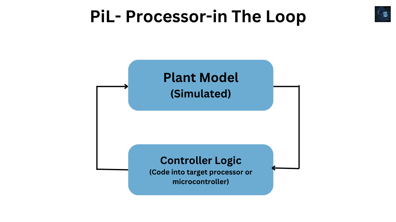
⚙️ Processor-in-the-Loop (PiL)
So, we’ve verified our algorithms in Model-in-the-Loop (MiL), and validated our generated code in Software-in-the-Loop (SiL). Now comes the exciting part — taking that same controller software and running it on the actual target processor.
This is the Processor-in-the-Loop (PiL) stage — where simulation meets the real embedded hardware for the very first time.
You can think of PiL as the bridge between software validation and hardware integration. In SiL, the controller code was running on a PC — a virtual execution environment. But in PiL, the controller code is now compiled, downloaded, and executed on the real microcontroller or processor that will be used in the actual ECU. The plant, however, still remains simulated.
So the setup looks like this:
- The plant model (representing the vehicle system, environment, or mechanical dynamics) runs on a PC.
- The controller software runs on the target processor — for example, a Texas Instruments C2000, Infineon Aurix, NXP S32, or Renesas RH850 microcontroller.
- Communication happens between them — typically over serial, CAN, or Ethernet interfaces — so that the plant sends simulated sensor data to the processor, and the processor sends back actuator commands.
This gives engineers a very realistic test setup — the same control software, running on the same embedded CPU, but still in a fully controllable, simulated world.
Now, why do we need PiL?
Because this is the first time we can measure how the real processor executes the control code. Every processor has its own quirks — instruction set architecture, clock speed, memory constraints, and timing behavior. Even if your code worked perfectly in SiL, it may behave differently on hardware due to timing delays, interrupt latencies, or numeric precision differences. PiL exposes those real-world effects early.
During PiL, engineers measure how long each control loop takes to execute — this is called execution time profiling. If a control algorithm must run every 1 millisecond but the processor takes 2 milliseconds to finish, you’ve got a performance issue. Finding that at this stage is critical, before integrating into the full ECU or vehicle.
Another reason PiL is so valuable is that it verifies compiler and hardware behavior. Compilers may optimize code differently, change variable arrangements in memory, or even alter the floating-point precision. By running the actual compiled binary on the target processor, we can detect subtle differences that might not appear in SiL simulations.
Let’s visualize this with an example. Suppose you’re developing a Throttle Control System for an electric vehicle. The control software reads pedal input, computes torque demand, and sends output commands to the motor controller. In PiL testing, the pedal position, motor speed, and torque sensors are simulated on your PC as part of the plant model. This simulated data is sent to your microcontroller via a communication link. The controller code executes its logic — on the real chip — and sends actuator signals back to the PC simulation, which updates the virtual plant accordingly.
If everything behaves as expected — throttle response, torque output, and timing all match the simulation — then your control software is validated at the processor level.
Another powerful aspect of PiL is profiling and optimization. Engineers use this stage to optimize CPU load, reduce execution time, and check memory footprint. They can evaluate:
- How much RAM and flash memory are consumed,
- How many CPU cycles are needed per control loop,
- And whether the code meets real-time constraints.
By doing this before full hardware integration, they ensure that the ECU will have enough processing power to handle all control tasks safely and efficiently.
Let’s also talk about communication latency — an important factor in real embedded systems. In SiL, data transfer between plant and controller is instantaneous. But in PiL, real communication interfaces are used — UART, CAN, SPI, or Ethernet. This introduces real-world timing delays. PiL testing helps measure and compensate for those delays to maintain stability and responsiveness of control loops.
Now, what kind of issues can PiL testing uncover?
You’d be surprised how often real processors reveal hidden bugs that software simulations miss. For example:
- Integer overflow in fixed-point arithmetic.
- Stack overflows or memory leaks.
- Compiler optimization differences affecting control outputs.
- Timing jitter caused by interrupt service routines.
- Real CPU load exceeding expected limits.
- Floating-point rounding variations.
PiL exposes all of these without the cost and complexity of full hardware integration.
Here’s another benefit — fault injection and diagnostic testing. Engineers can inject simulated faults (like sensor noise or signal dropouts) and observe how the real processor’s software handles them. Does it detect the fault? Does it switch to backup logic? Does it log diagnostic codes correctly? These behaviors are critical for automotive functional safety and ISO 26262 compliance.
Speaking of ISO 26262 — PiL testing is a key step in safety-critical software development. It provides concrete evidence that the software behaves as intended when compiled and executed on the target hardware platform. Many OEMs and Tier-1 suppliers use PiL results as part of their safety documentation and verification reports.
Let’s list 10 key things typically verified in PiL testing — the checklist every embedded developer lives by:
- Processor execution timing – verifying loop times, task scheduling, and CPU load under realistic conditions.
- Numerical precision – ensuring results match SiL within acceptable tolerances, accounting for floating/fixed-point differences.
- Compiler optimization behavior – checking that different compiler settings don’t change control outcomes.
- Memory usage and stack behavior – verifying static and dynamic memory allocations, preventing overflows.
- Interrupt latency – measuring how quickly the processor responds to simulated events.
- Code performance under load – simulating heavy data throughput or concurrent tasks to test stability.
- Task prioritization and real-time response – ensuring high-priority control tasks always execute on time.
- Communication timing – validating delays over UART, CAN, or Ethernet interfaces between plant and processor.
- Error and exception handling – ensuring graceful recovery from unexpected processor or data faults.
- Power consumption profiling – measuring processor energy usage for low-power embedded applications.
Each of these gives developers confidence that the embedded code isn’t just correct — it’s efficient, stable, and hardware-ready.
Now, an important note: in some setups, PiL and HiL are closely related. The main difference is that in PiL, only the processor is real — not the entire ECU or sensors. The rest (plant, environment, sensors, actuators) remains simulated. HiL, which we’ll explore next, takes this a step further by connecting everything to real hardware interfaces and physical I/O.
Another reason PiL is so powerful is that it allows developers to do closed-loop debugging. Because the processor communicates continuously with the simulation, you can step through code, set breakpoints, or inspect variables in real-time while the system runs. This visibility makes it far easier to understand timing behavior and fix subtle bugs that would be hard to trace in a complete hardware setup.
PiL environments can also be fully automated. Using tools like MATLAB/Simulink Real-Time, dSPACE MicroAutoBox, or ETAS INCA with embedded target interfaces, engineers can script PiL tests, collect logs, and compare them automatically with SiL and MiL reference results. If discrepancies appear, they can immediately isolate whether the issue came from the processor, the compiler, or the algorithm itself.
Here’s a quick example from the automotive world — testing a Motor Control Unit (MCU) for an electric power steering system.
The control algorithm, implemented in C, runs on a TI C2000 microcontroller. The virtual steering system (vehicle dynamics, steering column, road load, and driver input) is simulated on the PC. The PC sends sensor data like torque and steering angle to the microcontroller via CAN. The microcontroller executes its control loop and sends back actuator current commands. Engineers monitor how closely the motor torque follows driver input, how quickly the control loop responds, and whether timing deadlines are met.
This PiL test confirms both functional correctness and timing performance. If the code runs reliably on the real processor under these conditions, it’s ready for integration into a full ECU prototype.
Another growing application of PiL is in multi-core and AUTOSAR systems. Many modern ECUs use multiple cores or even multiple processors running in parallel. PiL helps analyze how these processors communicate, synchronize tasks, and share data — all before physical vehicle tests.
Finally, one of the biggest advantages of PiL is cost savings and safety.
Running the software on the target processor while keeping the environment virtual means no risk of damaging hardware or vehicles. You can test dangerous scenarios — sensor failures, extreme loads, or corner cases — completely safely, without putting real components at risk.
To summarize, Processor-in-the-Loop testing ensures that your control software not only works in theory but also performs as expected on real embedded silicon. It validates execution timing, memory usage, and computational precision, providing a crucial confidence layer before full hardware deployment.
So in short —
- MiL verifies your algorithms.
- SiL validates your software.
- And PiL proves your processor performance.
Once you’ve passed the PiL stage, your control code is ready to face the real world — the next step being Hardware-in-the-Loop (HiL), where your controller hardware interacts with real signals, sensors, and actuators in a physical test setup.
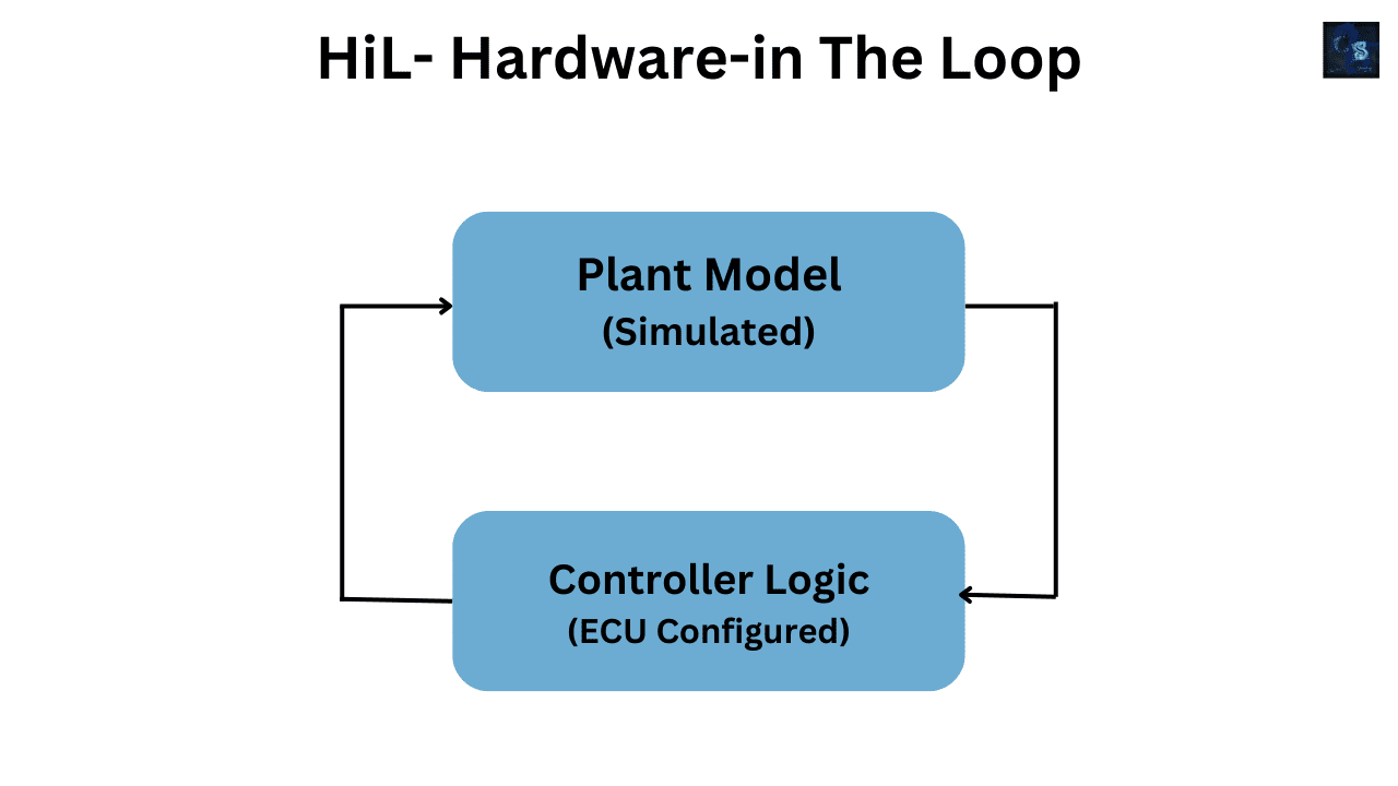
⚙️ Hardware-in-the-Loop (HiL)
Now that we’ve validated our algorithms in MiL, confirmed our software behavior in SiL, and verified real-time performance on the actual processor in PiL, we’re ready for one of the most powerful and critical stages in automotive testing — Hardware-in-the-Loop, or simply HiL.
HiL is where the real ECU hardware — the same one that will go inside the vehicle — meets a virtual world.
It’s the bridge between pure simulation and real-world testing.
This is where engineers connect their actual electronic control unit (ECU) to a real-time simulated environment that mimics the entire vehicle and its surroundings — the sensors, actuators, engine, wheels, brakes, and even driver inputs.
In short, HiL testing answers a crucial question:
👉 “Will my real ECU behave correctly when it’s finally inside the car?”
Let’s break this down step by step.
In a typical HiL setup:
- The ECU — the real hardware controller — runs the embedded software, just like it would in the vehicle.
- The plant model, which simulates the vehicle’s dynamics, environment, and components, runs in real-time on a dedicated simulation computer.
- The HiL simulator acts as a virtual car. It sends simulated sensor data (like wheel speed, temperature, throttle position, or battery voltage) to the ECU, and receives actuator signals (like injector commands, PWM duty cycles, or relay triggers) back from it.
To make this happen, the simulator is connected to the ECU using real interfaces — CAN, LIN, FlexRay, Ethernet, SPI, analog and digital I/O, and even PWM signals. The timing is real, the signals are real, but the vehicle is simulated.
So, you’re testing the ECU as if it were installed in a car — only you’re sitting safely in a lab.
HiL systems are typically built using specialized platforms like dSPACE, NI VeriStand, Vector VT System, or ETAS LABCAR. These platforms can run complex plant models — engine thermodynamics, vehicle dynamics, braking, electric drives, battery systems — all in real time.
Now, why is HiL so important?
Because this is the first stage where all software, hardware, and communication come together under realistic conditions. You’re testing the real ECU hardware, the actual compiled code, and the same network communication setup that will exist in the vehicle — but without needing the actual car or physical environment.
This allows engineers to safely verify safety-critical systems, such as braking, steering, airbag deployment, battery management, or autonomous driving functions, long before the prototype vehicle is ready.
Let’s take an example: imagine we’re developing an Electric Vehicle Battery Management System (BMS).
In a HiL setup, the real BMS ECU is placed on the bench. The HiL simulator provides virtual battery cell voltages, temperatures, and current readings. When the BMS commands a relay to open or close, the HiL system reacts instantly by simulating the battery’s electrical behavior.
Engineers can simulate thousands of driving cycles, faults, and environmental conditions — all without touching a real car.
Now, let’s look at what HiL helps verify in detail.
✅ 10 Things Verified in Hardware-in-the-Loop (HiL):
- ECU Functionality in Real Time – ensuring all control algorithms behave correctly under realistic operating conditions.
- I/O Signal Integrity – verifying analog, digital, PWM, and communication signals between ECU and simulated sensors/actuators.
- Real-Time Performance – checking if ECU tasks and interrupts meet real-world timing deadlines.
- Communication Network Testing – validating CAN, LIN, FlexRay, and Ethernet message timing, IDs, and data consistency.
- Sensor and Actuator Interface Behavior – ensuring signals match expected levels, scaling, and fault responses.
- Fault Injection and Diagnostics – simulating open circuits, short circuits, signal dropouts, and checking diagnostic trouble codes (DTCs).
- Safety and Redundancy Behavior – verifying fail-safe transitions, watchdog recovery, and safe state entry.
- Environmental and Load Testing – emulating temperature effects, power supply variations, and sensor drift.
- Closed-Loop Control Validation – confirming that the ECU maintains stability, response, and performance in simulated vehicle conditions.
- Functional Safety Verification – ensuring compliance with ISO 26262 safety standards through repeatable, traceable tests.
HiL testing is also where fault injection becomes incredibly powerful.
In real vehicles, you can’t easily simulate a wheel-speed sensor failure or a short circuit in the throttle signal. But in HiL, you can do this safely.
Engineers inject faults like:
- Open/short circuits on sensor lines.
- Voltage drops.
- Communication timeouts on CAN or LIN.
- Stuck actuators or delayed responses.
The goal is to confirm that the ECU detects and reacts appropriately — for instance, by switching to limp-home mode, triggering a diagnostic code, or cutting off power to protect the system.
HiL also supports test automation.
You can run thousands of test cases automatically overnight.
The system logs all ECU outputs, compares them to expected results, and generates a complete test report.
This is essential for regression testing — every time a new software version is released, it can be validated instantly against hundreds of predefined scenarios.
Another critical advantage is reproducibility.
In vehicle tests, road conditions and driver behavior constantly change. But in HiL, every test can be repeated exactly the same way, down to the millisecond.
This consistency is crucial when verifying timing behavior, safety functions, or compliance requirements.
Let’s also talk about real-time execution.
HiL systems must operate in hard real time — meaning they simulate the vehicle’s dynamics at the same rate the ECU expects real signals. If the ECU runs a 1 kHz control loop, the HiL simulator must update all relevant signals every millisecond without delay.
That’s why HiL simulators use powerful real-time CPUs or FPGAs — ensuring deterministic timing and no latency, even for complex multi-domain simulations like hybrid vehicles or autonomous systems.
HiL is also the stage where engineers verify network-level integration.
Modern vehicles have dozens of ECUs communicating over CAN, LIN, FlexRay, or Ethernet. HiL setups can simulate the entire in-vehicle network.
This allows testing of message prioritization, bus load, arbitration, and data consistency between ECUs — before actual in-vehicle wiring harnesses are built.
Let’s take another example — testing an Electronic Stability Control (ESC) system.
In HiL, the real ESC ECU is connected to a simulator that models the car’s suspension, wheel speeds, brake pressures, and steering inputs. Engineers simulate emergency maneuvers like sudden braking or oversteer. The ECU responds by activating brakes and adjusting torque, and the simulator reacts by updating vehicle motion in real time.
This closed-loop behavior shows whether the ESC logic correctly stabilizes the vehicle — all without a single physical wheel moving.
HiL setups can also integrate real hardware sensors or actuators — this hybrid testing is sometimes called “semi-physical simulation.”
For example, you can use a real temperature sensor or current sensor connected to the ECU while keeping the rest of the system simulated.
This gives even higher realism for critical components.
When it comes to data analysis, HiL platforms provide full traceability. You can record every signal, variable, and CAN message during tests.
This helps engineers identify subtle issues like timing jitter, unexpected voltage drops, or incorrect scaling — long before field testing.
And speaking of safety — HiL is absolutely essential for ISO 26262-compliant automotive software. It provides the test evidence for hardware-software integration verification, safety mechanism validation, and fault tolerance checks. Every fault injection, diagnostic behavior, and recovery response can be documented precisely — something not feasible with real-vehicle testing.
HiL is also a key step in continuous integration (CI) for automotive software.
Modern development pipelines automatically build software, deploy it to a HiL bench, run regression tests, and push results to dashboards.
This speeds up development, reduces human error, and ensures consistent quality with every software iteration.
Now, let’s not forget cost and safety benefits.
Running thousands of kilometers of virtual tests in HiL can replace months of expensive prototype vehicle testing. You can test rain, snow, extreme braking, or even sensor faults — all safely and repeatedly in the lab.
In short, HiL gives you the confidence that your ECU will work perfectly when it’s finally installed in the car.
🎯 Example:
Testing an Electric Power Steering (EPS) system.
The actual EPS ECU is connected to a HiL simulator that models steering torque, road feedback, and driver input. Engineers simulate lane changes, rough roads, and parking maneuvers.
They verify that steering assist behaves smoothly, torque feedback is accurate, and no faults occur under extreme loads.
All of this — before the ECU even touches a real steering column.
To summarize:
- Model-in-the-Loop (MiL) — early algorithm design and simulation.
- Software-in-the-Loop (SiL) — validating actual code in simulation.
- Processor-in-the-Loop (PiL) — verifying performance on the real microcontroller.
- Hardware-in-the-Loop (HiL) — testing the actual ECU in a simulated but real-time vehicle environment.
HiL is the final validation stage before vehicle-level testing. It’s where you gain full confidence that your ECU software and hardware work flawlessly, safely, and in real time — ready for integration into a real vehicle.
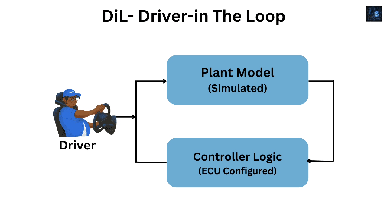
🧠 Driver-in-the-Loop (DiL)
We’ve come a long way — from pure simulations in MiL and SiL to testing real processors in PiL and full ECUs in HiL.
Now, we introduce something truly human — the Driver.
Welcome to the world of Driver-in-the-Loop (DiL) — the stage where the human element joins the test loop.
While MiL, SiL, PiL, and HiL focus on machines, DiL brings in the driver to see how the person behind the wheel interacts with all that technology.
So what exactly is DiL?
In simple terms, Driver-in-the-Loop is a test setup where a real human driver interacts with a driving simulator — a virtual environment that combines realistic vehicle dynamics, visuals, and feedback systems — all connected to the same control software and ECUs you’ve been testing through the earlier stages.
This stage bridges the gap between lab-based hardware tests and real-world road tests.
It’s about answering one key question:
👉 “How does the human driver perceive, react to, and influence the vehicle’s control systems?”
Because at the end of the day, no matter how advanced your algorithms are — whether it’s for steering assist, braking, or autonomous driving — they all must feel natural, intuitive, and safe to the human sitting behind the wheel.
Let’s break down how this setup works.
⚙️ How DiL Works
Imagine a driver sitting inside a motion-based simulator cockpit — complete with steering wheel, pedals, dashboard, and screens that project a 360° view of a virtual environment.
Now, inside that simulator:
- The vehicle model (plant) runs in real time — simulating vehicle dynamics, tire models, and environment physics.
- The ECUs or control software are connected — either real hardware from HiL setups or their virtual counterparts.
- The driver interacts naturally — accelerating, braking, steering, reacting to visuals and forces.
The entire system operates in a closed loop. The driver provides inputs, the vehicle model and ECUs respond, and those reactions are fed back to the driver through visuals, motion, and haptic feedback.
This forms a real-time human-machine system.
It’s like a video game, but with full engineering precision and real automotive control logic running underneath.
🎯 Why DiL Testing Matters
So why is DiL so important?
Because even if your ECU works perfectly in a lab, it might not feel right to a human driver.
For example, suppose your Electric Power Steering (EPS) system works flawlessly in HiL — but when a driver uses it, they feel the steering is too light at high speeds or too stiff at low speeds. That’s a human perception issue — something you’ll never catch with hardware or code alone.
DiL testing helps engineers evaluate exactly that — how humans perceive, react, and adapt to the vehicle’s behavior.
It’s essential for systems like:
- ADAS (Advanced Driver Assistance Systems) – lane keep assist, adaptive cruise control, and automatic emergency braking.
- Electric Power Steering and Braking Systems – tuning feedback and control feel.
- Autonomous and Semi-Autonomous Vehicles – studying driver handover behavior.
- Vehicle Dynamics Control – ensuring smooth transitions during cornering, acceleration, and braking.
In short, DiL combines engineering accuracy with human experience.
✅ 10 Things Verified in Driver-in-the-Loop (DiL):
- Human-Machine Interface (HMI) Usability – evaluating how drivers interact with displays, buttons, alerts, and menus.
- Driver Reaction and Response Time – measuring how quickly a driver reacts to hazards, warnings, or control changes.
- ADAS Feedback Quality – tuning lane-keeping assist, adaptive cruise, and braking alerts for comfort and confidence.
- Vehicle Dynamics Perception – verifying how real drivers feel steering, braking, and throttle behavior under different conditions.
- Comfort and Ergonomics Testing – analyzing motion cues, vibration levels, and seat dynamics during simulation.
- Driver Workload and Stress Analysis – using biometric data (heart rate, eye tracking) to measure cognitive load.
- Safety System Effectiveness – validating how quickly drivers take control during emergency situations.
- Driver Behavior Modeling – collecting data to refine virtual driver models for automated system calibration.
- Training and Validation of Autonomous Systems – observing how drivers respond to AI-driven maneuvers.
- System Tuning for Realism – adjusting steering assist curves, braking feel, and throttle response to match real-world comfort.
🚘 Example Scenario:
Let’s imagine you’re testing a Lane Keep Assist (LKA) feature.
In HiL, you validated that the ECU keeps the car within the lane using camera and steering torque inputs.
But in DiL, you put a real driver in a simulator, with a curved highway scene and realistic road textures.
Now, as the car drifts slightly from the center, the LKA system nudges the steering wheel.
How does the driver feel that correction?
- Is it smooth or abrupt?
- Does it build confidence or cause surprise?
- Does the driver trust the system or switch it off?
These are insights only DiL testing can reveal.
Engineers record steering torque feedback, driver control inputs, vehicle trajectory, and even facial expressions to understand driver comfort and system acceptance.
If the steering correction feels too aggressive, engineers fine-tune control parameters and re-test — all without ever leaving the simulator.
⚙️ The Technology Behind DiL Simulators
Modern DiL simulators are incredible pieces of engineering.
They include:
- Motion platforms with 6 degrees of freedom — simulating acceleration, braking, and cornering forces.
- High-resolution panoramic screens or VR headsets for realistic visuals.
- Force feedback steering wheels and pedals that replicate road feel and vibration.
- Eye-tracking and biometric sensors to analyze driver attention.
- Integrated HiL systems so that real ECUs can drive the virtual vehicle.
In fact, many OEMs like BMW, Ford, Volvo, and Tesla use DiL simulators to test driver comfort, ADAS tuning, and even autonomous control logic — long before building prototypes.
📊 Data from DiL Testing
DiL testing isn’t just about human feedback — it’s also about data.
Engineers record hundreds of variables:
- Vehicle position, yaw rate, and acceleration.
- Steering torque and driver input angle.
- Eye gaze direction and reaction time.
- Heart rate or galvanic skin response to measure stress.
This data helps correlate vehicle behavior with driver response — forming the foundation for future driver assistance algorithms.
For example, by analyzing where drivers look before lane changes, engineers can design better warning systems that predict driver intent rather than just react.
🔐 Safety and Validation
DiL testing also plays a critical role in functional safety and human factors validation.
When developing ISO 26262-compliant ADAS or autonomous systems, you must prove not only that the system works — but also that it interacts safely with human behavior.
Through DiL testing, you can analyze:
- When the driver takes over control.
- How long it takes for them to stabilize the car.
- Whether they understood system warnings correctly.
Such studies ensure that automation is not only safe — but also intuitive and predictable for real users.
🌍 Cost, Safety, and Flexibility
DiL offers tremendous benefits:
- You can simulate dangerous scenarios — icy roads, tire blowouts, or pedestrian crossings — safely in a lab.
- You can test hundreds of drivers and gather diverse behavioral data without using a single real vehicle.
- It drastically reduces prototype costs and accelerates development for ADAS and autonomous systems.
In essence, DiL merges engineering validation with human experience, ensuring that the vehicle’s intelligence and the driver’s instincts work together harmoniously.
🧩 Summary:
So, to recap:
- MiL verifies your algorithms in a virtual model.
- SiL tests your real code in a simulated environment.
- PiL validates your code on the target processor.
- HiL confirms your ECU works with real hardware connections.
- DiL ensures your driver trusts and understands your vehicle’s behavior.
It’s the stage where engineering meets psychology — where zeros and ones translate into confidence and comfort behind the wheel.
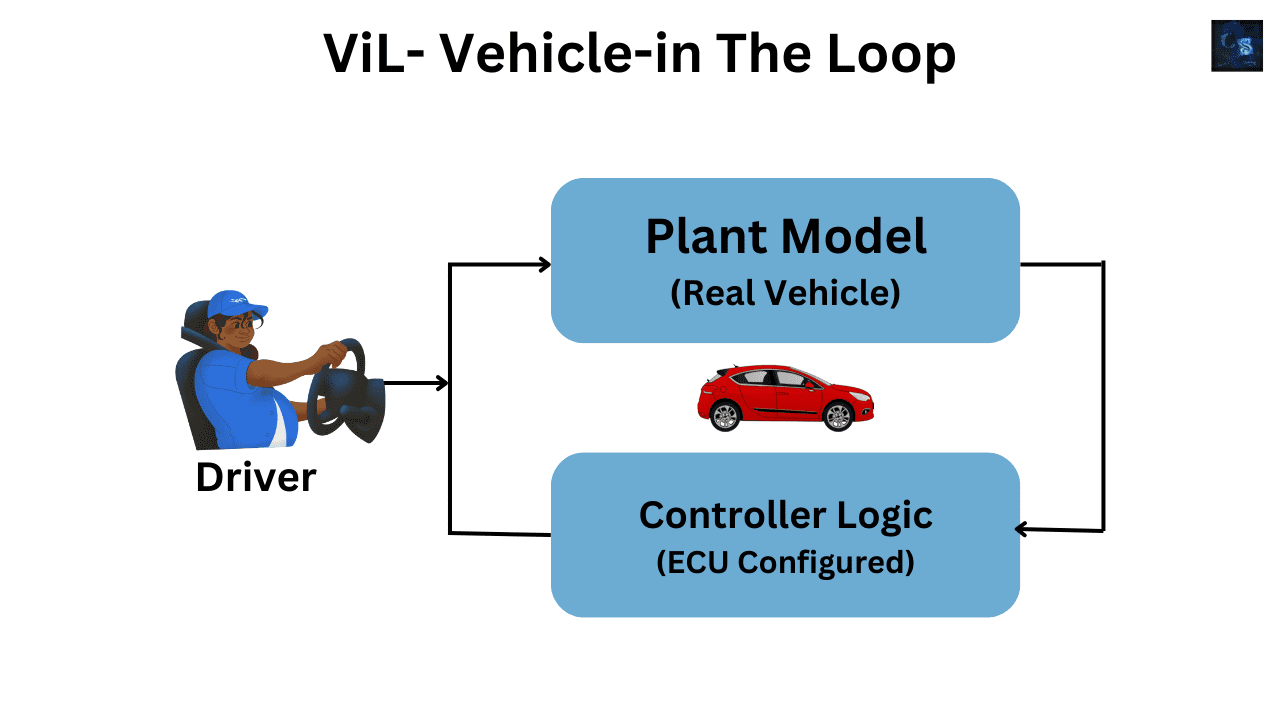
🚗 Vehicle-in-the-Loop (ViL)
We’ve now reached the final validation stage in the model-based design journey —
where virtual meets reality, and simulation finally touches the road.
Welcome to Vehicle-in-the-Loop, or ViL —
the phase where a real vehicle interacts with a simulated world to test systems safely and accurately before they hit the street.
If MiL and SiL were software-based, and HiL was hardware-based,
then ViL is the hybrid bridge — it combines the real car with virtual environments and test systems.
In simple words —
the vehicle becomes part of the loop.
It’s physically running, but the world it drives in — the traffic, obstacles, pedestrians, road conditions — can all be simulated in real time.
🧩 What is ViL?
Imagine your test car parked in a lab or on a test track.
Inside that car sits the same ECU, sensors, and actuators that will go into production.
But instead of driving on real roads, the inputs to those sensors — like radar echoes, GPS signals, or camera feeds — come from a simulation computer.
So, the ECU thinks it’s driving through a real environment,
while in reality, everything around it is being fed digitally.
This is the Vehicle-in-the-Loop concept —
a controlled fusion of the real and virtual worlds.
The car runs exactly as it would on the road,
but engineers can test dangerous or rare conditions —
like a pedestrian suddenly crossing, black ice on the road, or a vehicle cutting in — without putting anyone at risk.
⚙️ How ViL Works
In a ViL setup, three main components work together:
- The Real Vehicle – equipped with production ECUs, sensors, and actuators.
- The Simulation Environment – generating road, weather, and traffic scenarios in real time.
- The Interface System – which connects the real vehicle signals with the virtual world, translating between physical and simulated domains.
The car’s sensors (like radar, LiDAR, or cameras) are either fed synthetic signals or connected to virtual sensor emulators.
For example:
- A radar sensor can receive simulated reflections from a digital car in front.
- A camera can get video input from a real-time 3D simulation engine like CarMaker or dSPACE ASM.
- The GPS system can be fed virtual coordinates as if the car is moving.
Meanwhile, the ECUs and actuators respond naturally — accelerating, braking, steering — just like in real driving.
These responses are fed back to the simulation environment, closing the loop.
Everything happens in milliseconds, maintaining real-time accuracy.
🎯 Why ViL Is So Important
ViL is the last stage before real-world validation — it ensures that all the systems, logic, and interactions work perfectly when everything comes together.
It’s especially critical for ADAS and autonomous vehicles,
where the system must interpret complex environments and make safety-critical decisions.
With ViL, engineers can test:
- Pedestrian crossings under rain or fog
- Sudden lane changes
- Stop-and-go traffic
- Emergency braking or evasive maneuvers
— all without risking real lives or damaging cars.
In essence, ViL lets you drive thousands of “virtual kilometers” safely in a lab,
while still collecting data as if the car was really on the road.
✅ 10 Things Verified in Vehicle-in-the-Loop (ViL):
- Sensor Fusion Accuracy – validating how radar, LiDAR, and cameras work together in mixed real–virtual scenarios.
- ADAS and Autonomous Logic – testing adaptive cruise, collision avoidance, lane centering, and emergency braking.
- Vehicle Dynamics Interaction – ensuring the control algorithms match actual mechanical behavior.
- Communication Bus Verification – checking CAN, LIN, or Ethernet data flow between ECUs in real-time conditions.
- Timing and Latency – verifying system delays between sensor detection and actuator response.
- Environmental Robustness – testing under simulated rain, fog, night lighting, or icy roads.
- Safety and Redundancy Validation – ensuring fail-safes work correctly when one sensor or ECU malfunctions.
- Human Interaction with Real Controls – measuring how the driver or operator feels during ADAS engagement.
- Closed-loop Vehicle Testing – verifying full control chain from perception → decision → actuation.
- Certification and Regulation Readiness – providing traceable, logged test data for compliance (ISO 26262, UNECE R157, etc.).
🚘 Example Scenario: ADAS Emergency Braking Test
Let’s say you’re testing Automatic Emergency Braking (AEB) on a prototype vehicle.
In ViL, the car is stationary inside the lab.
Its radar sensor is connected to a simulator that generates a virtual road scene — a vehicle ahead slowing suddenly.
The radar “sees” that digital car and sends distance data to the ECU.
The ECU calculates that a collision is imminent and activates the brakes.
Even though there’s no real vehicle ahead, the braking system reacts exactly as it would in real life.
Engineers observe brake pressure buildup, timing delays, and ECU decision-making —
all while keeping the test perfectly safe and repeatable.
🧠 The Power of Mixed Reality
ViL isn’t just simulation — it’s mixed reality engineering.
It allows engineers to fine-tune systems that depend on both the physical world and digital perception.
Think about autonomous driving, where decisions rely on camera, radar, and LiDAR interpretation.
If those systems fail to recognize a shadow, reflection, or unusual object, the result could be dangerous.
ViL lets you recreate those edge cases —
from dazzling sunlight hitting a camera lens to unexpected objects on the road —
so algorithms can be improved before real testing.
🧩 Integration with Other Loops
ViL doesn’t work alone — it’s part of a chain.
Each loop feeds into the next:
- MiL ensures your control algorithms behave logically.
- SiL checks that your code runs correctly.
- PiL validates the code on the real processor.
- HiL connects your ECU to real hardware.
- DiL brings in the human driver.
- ViL connects the entire car to the virtual world.
After ViL, you move to real-world proving grounds or public-road validation,
but by then, 95% of the issues are already caught and solved.
That’s the power of model-based development —
you move from idea to vehicle safely, efficiently, and confidently.
🧰 Tools and Platforms Used for ViL
Some of the most popular ViL setups and tools in the automotive world include:
- dSPACE Automotive Simulation Models (ASM)
- IPG CarMaker
- NI VeriStand
- Vector CANoe.Car2x
- ETAS LabCar ViL Systems
- AVL DRIVINGCUBE™
These systems connect simulation computers with real vehicle ECUs, sensors, and actuators using ultra-low-latency interfaces.
They’re capable of generating full traffic environments with 3D visuals, road geometry, pedestrians, and weather —
all synchronized with the real vehicle’s control systems.
🌍 Benefits of Vehicle-in-the-Loop Testing
- Safety – Simulate dangerous scenarios without physical risk.
- Cost Efficiency – Reduce prototype and track-testing expenses.
- Repeatability – Test the same event hundreds of times for validation.
- Regulatory Compliance – Generate detailed test evidence for certification.
- Speed to Market – Shorten development time through early issue detection.
In short, ViL helps manufacturers validate vehicles faster, safer, and smarter.
🎬 Final Chapter – From Code to Car: The Complete Journey of Testing in Automotive
Let’s take a moment and step back.
We started this journey with an idea — a line of code, a control strategy, or maybe just an algorithm on paper.
And through six powerful stages — MiL, SiL, PiL, HiL, DiL, and ViL — that idea transformed into a working, intelligent vehicle system.
🧩 Let’s Recap This Engineering Evolution
It all began with Model-in-the-Loop (MiL) —
the stage of imagination and creation.
Where engineers test ideas inside pure simulation — no hardware, just logic, equations, and imagination.
Here, algorithms learn to breathe for the first time.
Then came Software-in-the-Loop (SiL) —
where that model becomes real code.
Now, the logic runs in compiled form, interacting with the virtual plant.
It’s the first time your design starts acting like real software.
Processor-in-the-Loop (PiL) takes it further —
the same code now runs on the target processor or microcontroller.
You start feeling the heartbeat of the hardware — measuring execution time, performance, and real-world computational limits.
Hardware-in-the-Loop (HiL) is where everything starts coming alive.
The ECU, sensors, and actuators come into play.
The plant remains simulated, but the controller hardware is real.
This is the engineer’s test track inside the lab — where you validate every signal, every fault, every safety logic before touching a real car.
Then, we added the Driver-in-the-Loop (DiL) —
where a human joins the loop.
Using simulators, steering wheels, pedals, and screens —
you observe how drivers interact with the system.
You see whether ADAS features like lane keeping or adaptive cruise feel natural and safe.
And finally, the grand stage — Vehicle-in-the-Loop (ViL).
Where the real car meets the virtual world.
Sensors, ECUs, and actuators interact with digital roads, weather, and traffic —
testing complex, risky situations safely in a lab environment.
It’s the final bridge between simulation and reality.
⚙️ The Bigger Picture: Why This Matters
These six loops are not just testing methods —
they are the backbone of automotive innovation.
Every airbag system, braking algorithm, or self-driving feature you see today —
was tested, refined, and validated across these loops before it ever touched asphalt.
They help engineers answer the hardest questions safely:
✅ What if the sensor fails?
✅ What if the ECU misses a signal?
✅ What happens when a driver panics, or the road turns slippery?
With MiL to ViL testing, engineers can simulate thousands of real-world miles in hours —
detecting faults, improving control strategies, and building confidence in every line of code.
This process saves lives, reduces costs, and accelerates innovation.
🚗 The Future of Automotive Testing
As vehicles evolve toward electrification and autonomy, these testing loops are evolving too.
Future cars won’t just be tested — they’ll be continuously verified using digital twins.
Imagine — your car collecting data while driving and feeding it back to a simulation model,
which then updates the algorithms through OTA (over-the-air) improvements.
That’s not science fiction anymore —
it’s happening now in R&D labs at Tesla, BMW, Bosch, and Continental.
Model-based development and virtual validation are becoming the DNA of intelligent mobility.
🔑 Takeaway: From Simulation to Street
Every great automotive innovation you experience —
from automatic braking to lane centering, battery management to adaptive lighting —
is built on this structured foundation of validation:
- MiL: Concept and control logic.
- SiL: Code-level verification.
- PiL: Processor timing and computation checks.
- HiL: Hardware and real-time testing.
- DiL: Human-integration and experience.
- ViL: Full vehicle integration in a simulated world.
Together, they form the complete loop of confidence —
where imagination becomes implementation,
and implementation becomes intelligence.
Well, That’s It
Also, read:
- “Mother of All Deals”: How The EU–India Free Trade Agreement Can Reshape India’s Economic Future
- 10 Free ADAS Projects With Source Code And Documentation – Learn & Build Today
- 100 (AI) Artificial Intelligence Applications In The Automotive Industry
- 1000+ Automotive Interview Questions With Answers
- 2024 Is About To End, Let’s Recall Electric Vehicles Launched In 2024
- 2026 Hackathons That Can Change Your Tech Career Forever
- 50 Advanced Level Interview Questions On CAPL Scripting
- 7 Ways EV Batteries Stay Safe From Thermal Runaway