Model-Based Design · Simulink · Stateflow · Style Standard
The MAAB / MAB
Modeling Guidelines
A complete, visually explained tutorial on the modeling style standard that governs how professional control software is built in Simulink and Stateflow.
01 — Orientation
What the MAAB / MAB guidelines actually are
When engineers build control software the modern way, they do not start by typing C code. They draw the algorithm as a block diagram in Simulink and draw the decision logic as a state machine in Stateflow, then let a code generator turn that model into embedded C. This approach is called Model-Based Design (MBD), and the model becomes the single source of truth for the whole team — requirements engineers, control engineers, test engineers, and the software that runs in the final product.
The moment a model is shared, a problem appears: a diagram is only as valuable as it is readable. Two engineers solving the same problem can produce two models that behave identically but look nothing alike — different naming, different layout, different block choices, tangled signal lines. One is a joy to review; the other is a maintenance liability. The MAAB / MAB guidelines exist to close that gap. They are a modeling style standard: a large, structured set of rules that specify how a Simulink and Stateflow model should be named, laid out, structured, and configured so that any qualified engineer can open it and understand it.
Formally, the MathWorks Advisory Board (MAB) guidelines stipulate basic rules for modeling in Simulink and Stateflow during the development of production software. Their stated purpose is to allow a simple, common understanding by both the people who create control-system models and the people who consume them. The three overriding objectives are readability, simulation & verification, and reliable code generation. Think of them as the model-based equivalent of a coding style guide like MISRA C or PEP 8 — but for pictures instead of text.
02 — History
From MAAB to MAB: a short history
The board began as the MathWorks Automotive Advisory Board (MAAB). Its inaugural meeting in July 1998 brought together three automotive giants — Ford, Daimler-Benz, and Toyota — to coordinate feature requests for MathWorks’ controls, simulation, and code-generation tools. The board is independent of MathWorks: the companies write the guidelines, and MathWorks hosts, maintains, and helps automate them but does not author them.
An early and enduring output of the board was the set of control algorithm modeling guidelines. Over successive releases the document grew and matured, with Version 3.0 becoming a widely cited industry reference. As adoption spread far beyond automotive — into aerospace, industrial, medical, and rail — the “Automotive” in the name became misleading.
The board therefore reorganised. Today the umbrella is the MathWorks Advisory Board, still abbreviated MAB, composed of an independent working group of major OEMs and suppliers across multiple industries. It contains two collaborating subgroups:
- NA-MAAB — the North American MathWorks Automotive Advisory Board, with manufacturers and suppliers from multiple industries across the US and Europe.
- JMAAB — the Japan MATLAB Automotive Advisory Board, with automotive manufacturers and suppliers in Japan, working closely with MathWorks.
Both subgroups contribute to the shared guideline set. In current tooling you will see two closely related published standards: the MAB guidelines and the JMAAB guidelines (recent versions such as JMAAB v5.1 and v6.0). Many rules are identical between them; where they diverge, the tooling provides version-specific checks. The classic “MAAB v3.0” terminology still appears in older projects and in legacy guideline IDs, which is why this tutorial refers to the standard as “MAAB / MAB” — you will encounter both names in the field.
03 — Motivation
Why the guidelines exist
The guidelines are important for project success and teamwork — both in-house and when cooperating with partners or subcontractors. A model that follows a shared standard can be handed between organisations without a lengthy “how do I even read this?” phase. Concretely, the guidelines are engineered to serve a handful of interlocking goals.
| Goal | What it means | Why it matters in practice |
|---|---|---|
| Readability | A model can be understood at a glance by someone who did not build it. | Reviews, audits, and handovers become fast and reliable; onboarding is quicker. |
| Maintainability | Changes are localised and safe to make. | Products live for a decade; the person maintaining the model is rarely the author. |
| Reusability | Subsystems and libraries can be dropped into other projects. | Reuse only works if interfaces and naming are predictable across teams. |
| Portability | Models behave consistently across MATLAB releases and targets. | Avoids surprises when moving between simulation, rapid prototyping, and production. |
| Verification & validation | The model structure supports testing, coverage, and traceability. | Required for safety standards; ambiguous constructs are hard to test to completion. |
| Code generation | The model produces clean, predictable, efficient C/C++. | Certain “legal” modeling choices generate poor or unsafe code; the rules steer around them. |
The economics of a readable model
It is worth dwelling on why readability dominates this list, because it is easy to dismiss as a soft concern. Consider the lifetime of a production control model. It is authored once, but it is then read hundreds of times — during peer review, during integration, during debugging, during safety assessment, during a feature change two years later by someone who has never seen it, and during a supplier audit. The cost of a model is overwhelmingly a reading cost, not a writing cost. Any effort spent making the model easier to write at the expense of reading is almost always a bad trade.
This is the same insight that drives coding style guides, but it bites harder in modeling because a diagram carries more incidental complexity than a line of text: layout, routing, block shapes, colours, and hierarchy are all degrees of freedom that two engineers will spend differently. Left unconstrained, that freedom produces models that are correct but mutually unintelligible. The guidelines deliberately remove degrees of freedom that carry no information — where a block name sits, which direction signals flow, how a state action is formatted — so that the remaining variation actually means something. When everything superficial is standardised, the reader’s attention is free to focus on the algorithm itself.
There is a second-order benefit: diffability. When models follow a consistent layout and naming discipline, version-control diffs between two revisions become meaningful — you can see what genuinely changed rather than being drowned in cosmetic churn. That, in turn, makes code review of model changes tractable, which is a prerequisite for treating models as real, version-controlled engineering artefacts rather than throwaway sketches.
There is also a human-factors insight baked into the standard. The working group explicitly recognised that rules which place a high burden on engineers will be ignored or subverted. That is why so much of the standard is automatable — a machine, not a reviewer, enforces the tedious parts — and why the rules are pitched at a pragmatic, conservative level rather than a purist one.
04 — Context
Where the guidelines fit in the workflow
Model-Based Design is usually drawn as a V-model: requirements flow down the left arm into design and modeling, code is generated at the bottom, and verification climbs back up the right arm. The MAAB / MAB guidelines act at the design & modeling stage — but because a clean model is what makes the right-hand verification arm tractable, their influence ripples across the entire V.
The practical consequence: a team that enforces the guidelines early spends far less effort on the right arm. Coverage tools work better on clean models, generated code reviews go faster, and traceability from a requirement to a block to a test is unambiguous. Skipping the guidelines does not save time — it defers and multiplies it.
05 — Structure of a rule
Anatomy of a single guideline
Every guideline in the standard is documented with the same fixed template. This consistency is itself part of the design: a reader can scan any rule and immediately know its identity, how strictly it must be followed, where it applies, and whether a tool can check it. Companies writing their own house rules are encouraged to reuse this exact template.
The template fields are as follows:
| Field | Purpose |
|---|---|
| Guideline ID | A stable, unique identifier (e.g. na_0004). Never reused, never changed, even if the rule text is revised. |
| Guideline Title | A short, stable name. Deliberately not a description, because descriptions change while titles must remain a durable reference. |
| Priority | How binding the rule is: Mandatory, Strongly Recommended, or Recommended. |
| Scope | Which body the rule belongs to — historically MAAB, and today MAB / JMAAB. |
| MATLAB Versions | Which product versions the rule applies to. Most apply to all versions; some are version-specific. |
| Prerequisites | Other guidelines that must be satisfied first (dependencies between rules). |
| Description | The rule itself, usually with compliant and non-compliant examples. |
| Rationale | Why the rule exists — readability, code generation, verification, and so on. |
| Last Change | The version in which the rule last changed, for traceability across releases. |
| Model Advisor Check | The automated check that verifies the rule, if one exists. |
Rendered as a “datasheet”, a real guideline looks like the card below. Throughout this tutorial, individual rules are shown in this format so you can see the standard’s own structure at work.
- Scope
- MAB / MAAB
- Versions
- All
- Description
- The visual appearance of a model — window state, zoom, block layout, and drop-shadow/appearance settings — should be consistent so that models open in a predictable, readable state.
- Rationale
- Consistent appearance makes models easier to read, diff, review, and hand over between teams.
- Check
- Model Advisor: “Check for consistent model appearance settings”
06 — Identifiers
Reading a guideline ID
Every rule has an ID of the form xx_nnnn — a two-letter prefix, an underscore, and a four-digit number, for example jc_0141 or db_0032. The prefix encodes who authored the rule and, loosely, its lineage. Understanding the prefixes helps you navigate the standard and recognise legacy rules.
| Prefix | Meaning | Status |
|---|---|---|
na | North American MAAB (NA-MAAB) authored | Active |
jc | JMAAB “common” / Japan-authored rules | Active |
db | Legacy prefix (early diagram/basic rules) | Reserved — no new rules |
jm | Legacy JMAAB prefix | Reserved — no new rules |
hd | Legacy prefix | Reserved — no new rules |
ar | Legacy prefix (e.g. file/archive naming) | Reserved — no new rules |
The legacy prefixes db, jm, hd, and ar are reserved: the committee will not write new rules with them, but existing rules keep their historical IDs so that references in older projects and papers remain valid. This is why an ID is treated as immutable — it is a permanent handle. In current Simulink Check tooling, the automated checks reference these IDs directly; for example a JMAAB v6 check appears with an ID like mathworks.jmaab_v6.jc_0009, while a classic MAAB check appears as mathworks.maab.na_0009.
07 — How binding is a rule?
Priority levels
Not all rules carry equal weight. Each guideline is assigned one of three priorities, which tell a team how much latitude they have and what the consequence of ignoring the rule is. This is one of the most practically important parts of the standard, because it lets an organisation adopt the mandatory core immediately and phase in the rest.
| Priority | Definition | Expected conformance | Consequence if violated |
|---|---|---|---|
| Mandatory | Rules that all companies agree are absolutely essential. | 100% conformance. | Essential items are missing; the model may not work properly, or code generation / verification is compromised. |
| Strongly Recommended | Agreed good practice; legacy models may prevent full compliance. | Conform to the greatest extent possible; 100% not required. | Adverse effect on maintainability, portability, and reusability. |
| Recommended | Rules that improve appearance but are not critical to running the model. | Preferred, not required. | Appearance does not match other projects; quality/consistency deteriorates. |
The waiver policy
The standard is pragmatic about exceptions. If a guideline is intentionally ignored, the reasons must be documented. This waiver discipline is what makes the standard auditable: a deviation is acceptable, but an undocumented, unexplained deviation is not. In a safety context the documented waiver becomes part of the evidence trail. In tooling, this maps onto check exclusions and justifications, which we cover in the Model Advisor section.
08 — The map
The category architecture of the standard
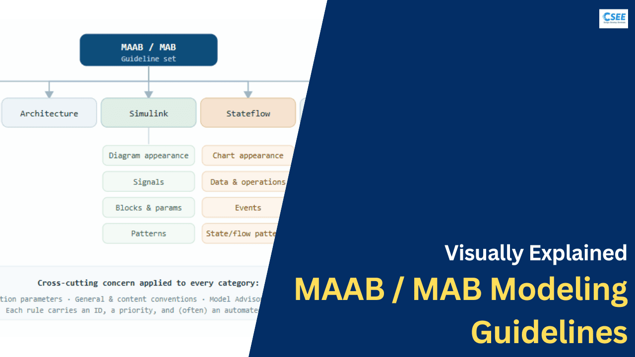
The guidelines are organised into a small number of top-level categories, each covering a distinct concern. The current MAB structure groups rules under Naming Conventions, Simulink (diagram appearance, signals, blocks, and patterns), Stateflow (chart appearance, data and operations, events, and patterns), and MATLAB (MATLAB Function appearance, data, and patterns). Earlier MAAB v3.0 editions also broke out Software Environment, Model Architecture, and Configuration Options as their own chapters. The mental map below is the one used throughout the rest of this tutorial.
The document’s own usage advice is that naming conventions and model architecture are foundational — they apply to every kind of model — while the Simulink, Stateflow, and MATLAB branches apply only when you use those constructs. We follow that order below, starting with naming.
09 — Foundations
Naming conventions
Names are the first thing a reader sees and the most common source of avoidable confusion. The naming rules govern what characters are allowed, how long names may be, and how names appear on models, subsystems, signals, blocks, parameters, and Stateflow objects. The recurring theme is portability: a name that is legal in one file system, one code generator, or one language may break in another, so the rules restrict names to a safe common denominator.
Allowed characters and length
The core character rule is consistent across object types: use letters, digits, and underscores; start with a letter; avoid spaces, leading/trailing underscores, double underscores, and reserved words. The reason is simple — these names must survive being turned into C identifiers and file names during code generation.
| Object | Rule of thumb | Representative ID |
|---|---|---|
| Model / file name | Letters, digits, underscores; must be a valid file name and identifier. | ar_0001 |
| Subsystem name | Descriptive; usable characters only; no leading/trailing/double underscore. | jc_0201 |
| Block name | Usable characters; single line preferred where practical. | jc_0211 |
| Signal / signal-line name | Usable characters; meaningful; consistent with the data it carries. | jc_0221 |
| Parameter name | Usable characters; consistent naming scheme across the project. | jc_0231 |
| Trigger / Enable port name | Named consistently to reflect the conditional they control. | jc_0281 |
- Description
- Subsystem names use letters (a–z, A–Z), digits (0–9) and underscores. Names do not start with a number, do not contain spaces, do not begin or end with an underscore, and do not contain two consecutive underscores.
- Rationale
- The subsystem name frequently becomes a function or file name in generated code; illegal identifiers break the build or force silent renaming that destroys traceability.
Compliant vs non-compliant names
Beyond legality, names must be meaningful and consistent. A signal carrying vehicle speed should not be called x3; a parameter for a maximum torque limit should be recognisably named the same way everywhere it appears. Consistency compounds: once a team’s vocabulary is predictable, readers stop translating and start understanding.
10 — Foundations
Model architecture
Architecture guidelines describe how a model is decomposed into layers and reusable units. A large control algorithm is never a single flat diagram; it is a hierarchy. The standard encourages a clean, layered decomposition in which each level has a single clear responsibility and interfaces between levels are explicit.
Decomposition building blocks
The standard leans on a handful of Simulink mechanisms to build this hierarchy, and has rules for each:
- Subsystems group related logic behind a single block. Virtual subsystems are purely visual; atomic subsystems form a real execution and code-generation boundary. Choosing the right kind matters for both behaviour and generated-code structure.
- Libraries hold reusable, version-controlled blocks. A block used in ten models should be one library block linked ten times, not ten copies — so a fix propagates everywhere.
- Model reference lets one model include another as a compiled component, enabling large-team parallel development and incremental builds.
- The data dictionary centralises signal definitions, parameters, and data types so that interfaces are defined once and shared, rather than redefined ad hoc in each model.
Virtual versus atomic subsystems
A subtlety that trips up newcomers is that not all subsystems are equal. A virtual subsystem is a purely visual grouping — Simulink dissolves it during execution, so it has no effect on behaviour or the structure of generated code; it exists only to tidy the diagram. An atomic subsystem, by contrast, is a real boundary: Simulink guarantees it executes as a unit, and it typically becomes a distinct function in generated code. The distinction matters because the same picture can mean two different things. If you intend a subsystem to become a reusable C function, it must be atomic; if you rely on execution order across a boundary, only an atomic subsystem gives you that guarantee. The guidelines push you to choose deliberately rather than accept the default, because an accidental virtual boundary can silently change generated-code structure and an accidental atomic boundary can silently change execution order.
When to reach for model reference
Subsystems and libraries handle decomposition within a model, but large programs need decomposition across models. Model reference lets one model include another as a separately compiled component. The pay-offs are significant on a big team: components can be developed and unit-tested in isolation, builds become incremental so you only recompile what changed, and clear ownership boundaries reduce merge conflicts. The cost is that interfaces between referenced models must be defined even more rigorously — which is exactly why the naming, data-dictionary, and interface guidelines matter most at these seams. As a rule of thumb, use subsystems for logical grouping inside a component, libraries for small reusable blocks, and model reference for the top-level architectural components that different people or teams own.
Libraries and the single-source-of-truth rule
The library discipline deserves emphasis because it is so often violated by copy-paste. When a useful block — say a debounce filter or a rate limiter — is needed in ten places, the wrong answer is ten copies, because a bug fix then has to be applied ten times and inevitably is not. The right answer is one library block linked ten times. A change to the library master propagates to every link automatically. This is the model-based expression of the “don’t repeat yourself” principle, and it is what makes reuse a genuine asset rather than a maintenance liability multiplied across the project.
11 — Foundations
Model configuration options
A Simulink model carries a large set of configuration parameters — solver type, data type overrides, diagnostic settings, hardware target, and code-generation options. Two behaviourally identical models with different configuration can simulate differently or generate very different code. The guidelines therefore specify that certain configuration settings be fixed to safe, consistent values, and that diagnostics which catch dangerous constructs be set to error rather than warning or none.
| Setting area | Guideline expectation | Reason |
|---|---|---|
| Solver | Fixed-step for code-generation targets. | Embedded targets run at fixed rates; variable-step solvers do not map to real-time execution. |
| Diagnostics | Critical diagnostics (e.g. algebraic loop, data-type mismatch) set to error. | Silently tolerated issues become field failures; failing early is safer. |
| Data type handling | Explicit types; avoid unintended double defaults on embedded targets. | Implicit doubles waste memory and CPU and can hide overflow bugs. |
| Hardware implementation | Match the real target’s word sizes and endianness. | Fixed-point and integer behaviour depends on the actual processor. |
| Optimisation / code style | Consistent, project-wide code-generation settings. | Reproducible, reviewable generated code across the team. |
Configuration is typically managed centrally with a shared configuration reference so that every model in a project points at the same settings object. That way a change to a diagnostic policy is made once and inherited everywhere, exactly as with the data dictionary for signals.
12 — Simulink
Simulink diagram appearance
This is the most visible part of the standard and the one that most improves day-to-day readability. The core principle is that a diagram should read like a circuit schematic or a book: signals flow predominantly left to right, feedback loops are the only signals allowed to run right-to-left, lines do not cross unnecessarily, blocks are aligned to a grid, and the overall picture is uncluttered.
The layout rules
- Signal flow direction: primary data flows left to right; feedback goes right to left. This single rule does most of the readability work.
- No overlapping blocks or lines: blocks do not sit on top of one another, and signal lines avoid crossing where routing can prevent it.
- Block name position & visibility: names appear in a consistent position (below the block) and are shown or hidden consistently per project (
db_0142,jc_0061). - Alignment & spacing: blocks align to a grid with even spacing, so the eye can track rows and columns.
- Consistent block types per level: a given level of the model uses consistent block styles rather than a scattershot mix (
db_0143). - Show key parameters: basic block parameters that affect behaviour are visible on the icon where practical (
db_0140).
The difference is dramatic in practice. Below, the same four-block signal chain is drawn twice — once following the rules and once ignoring them.
- Description
- Block names are placed below the block, consistently across the model, rather than above or beside it.
- Rationale
- A predictable name position lets a reader scan a diagram without hunting for labels, and keeps diffs stable when blocks move.
13 — Simulink
Signals & data flow
Signals are the wires of the model. The signal rules make data flow traceable: you should be able to follow any value from its source to its destinations and know what it represents. The two big themes are labeling and disciplined use of hidden connections (Goto/From and Data Store blocks).
Labeling and label propagation
Important signals should be named, and there is a specific rule about where a label may be attached versus where it may only be propagated. A label is entered at the signal’s source (the block output that defines it) and then propagated downstream, rather than being re-typed at random points. This distinction (see na_0008, na_0009) keeps a single authoritative name for each signal and prevents contradictory labels on the same wire.
- Description
- A signal label is entered only at the signal source. Downstream, the same name is shown via label propagation, not re-entered.
- Rationale
- Guarantees one authoritative name per signal; eliminates conflicting labels and makes refactoring safe.
- Note
- This is one of the few checks that does not apply to AUTOSAR modeling in current tooling.
Hidden connections: Goto/From and Data Stores
Simulink offers ways to connect blocks without a visible wire — Goto/From tags and Data Store Memory/Read/Write blocks. These are powerful but dangerous for readability, because they create data flow you cannot see. The guidelines therefore restrict their scope: a Goto/From pair should be local where possible (na_0011), and data stores should be used deliberately and with limited scope (jc_0161). The default should always be a visible signal line; hidden connections are the exception, justified only when a wire would genuinely harm the diagram.
Buses and grouping
When many related signals travel together — say all the outputs of a sensor-conditioning subsystem — they should be grouped into a bus rather than run as a dozen parallel wires (na_0010). A bus is the model-level equivalent of a struct: it keeps related data together, cleans up the diagram, and produces a tidy interface in generated code.
db_0081). Every port should be connected or explicitly terminated with a Terminator/Ground block — an unconnected line is almost always a bug or an unfinished thought.
14 — Simulink
Block usage & parameters
Individual blocks have their own rules, because a block that is convenient to place is not always safe to generate code from. These rules pin down how common blocks must be configured so their behaviour is unambiguous and their generated code is clean. The table gathers the most frequently cited block rules.
| Block | Guideline in plain terms | ID |
|---|---|---|
| Sum | Use rectangular shape for many inputs; make signs and input order explicit; avoid ambiguous round icons for complex sums. | jc_0121 |
| Relational Operator | Compare in a consistent orientation; the block output is a clear boolean; avoid comparing signals of mismatched types. | jc_0131 |
| Switch | The control (middle) input drives selection; the threshold and criterion are set explicitly and readably. | jc_0141 |
| Data Store Memory / Read / Write | Use with restricted scope and clear ownership; prefer signal lines when practical. | jc_0161 |
| Constant | Value and data type set explicitly; named parameters preferred over magic numbers. | db_0140 |
| Port blocks | Inport/Outport numbering is sequential and their names are visible & meaningful. | db_0042, na_0005 |
- Description
- The Switch block passes the first or third data input based on the second (control) input and an explicit criterion/threshold. The criterion is set so the selection logic is obvious from the icon.
- Rationale
- An explicit criterion removes ambiguity about which branch is chosen and produces readable, predictable generated code (a clean
if/else).
Show the parameters that matter
Guideline db_0140 asks that basic block parameters be displayed on the block where practical. If a Gain block multiplies by Kp, seeing Kp on the icon means a reader never has to open the dialog to understand the diagram. The same logic applies to constants, saturation limits, and switch thresholds. Visible parameters turn a diagram into self-documenting artefact.
15 — Simulink
Simulink modeling patterns
Beyond individual blocks, the standard blesses certain patterns — canonical ways to build common logic. Patterns matter because there are many “legal” ways to express, say, an if/else in Simulink, and only some of them produce clean code and clear diagrams.
Logical constructs
Guideline na_0003 promotes a simple, consistent pattern for logical constructs built from logical blocks (AND, OR, NOT). Compound conditions should be assembled from clearly separated logical blocks rather than crammed into one over-configured block, so a reviewer can read the boolean expression off the diagram like an equation.
Conditional execution: If / Switch-Case subsystems
For control flow, the standard prefers explicit If and Switch Case blocks driving action subsystems, rather than arithmetic tricks that fake branching. This makes the mutually-exclusive nature of the branches visible and generates a natural if/else if/else or switch in C.
Saturation and range limiting
Limiting a value to a range is so common it has canonical patterns — a Saturation block, or a MinMax construct — configured with explicit, named limits. The anti-pattern is a hand-built cascade of relational operators and switches that does the same thing less readably.
Avoid algebraic loops
An algebraic loop — a signal that depends on itself within one time step without a delay — is both hard to reason about and hard to generate code for. The standard (with db_0110) steers you to break such loops explicitly with a unit delay, and configuration guidelines set the algebraic-loop diagnostic to error so the tool refuses to let one slip through silently.
16 — Stateflow
Stateflow guidelines
Where Simulink expresses continuous and periodic data flow, Stateflow expresses modes, decisions, and sequencing — the finite-state and flow-chart logic of a controller. Stateflow is extremely expressive, which is precisely why it needs disciplined rules: an unconstrained chart can become an unreadable, untestable tangle. The Stateflow guidelines cover chart appearance, data and operations, events, and canonical state-chart and flow-chart patterns.
Chart appearance
The appearance rules mirror the Simulink ones. States are laid out cleanly without overlap, transitions are drawn as clear arcs rather than crossing spaghetti (db_0129), and there is exactly one default transition per level, placed predictably (usually top, per jc_0531) so the reader instantly knows the entry state.
States, actions, and formatting
State names are meaningful. Actions inside a state follow a fixed format — entry:, during:, and exit: actions are written explicitly (jc_0501) rather than relying on implicit defaults, so a reader knows exactly when each action runs. Deeply nested states are avoided where a flatter structure is clearer, and the number and depth of states are kept reasonable (db_0137).
- Description
- Each hierarchical level with exclusive (OR) states has a single default transition, drawn from the top and clearly pointing to the entry state.
- Rationale
- The entry state must be unambiguous. A single, predictably placed default transition tells the reader where execution begins without analysis.
Data and operations
Stateflow can read and write model data, so the standard governs the interface between Stateflow and Simulink (db_0122), the scope of internal variables (db_0126), and how comparisons and operators are written (na_0013). Comparisons should use explicit, type-safe forms; mixing signed and unsigned or integer and float without thought is discouraged for the same reason as in Simulink — it hides overflow and rounding bugs.
Events
Events drive chart execution, but excessive or broadcast events make control flow hard to follow. The event guidelines encourage restrained, explicit event use over implicit or broadcast-heavy designs, so that when a chart runs and why a transition fires remain readable.
Flow-chart patterns vs state-chart patterns
Stateflow supports two distinct styles. State charts model modes with states and transitions (the diagram above). Flow charts model decision logic with junctions and conditional transitions — closer to a classic flowchart. The standard defines clean patterns for both: flow-chart transitions should form well-structured decisions (with a clear condition on each branch, per db_0132), and graphical functions should set their return value in a single, clear place (jc_0511, jc_0521). Mixing the two styles carelessly in one chart is the usual readability trap.
Hierarchy and parallelism
Stateflow lets states contain other states (hierarchy) and lets states run concurrently (parallelism, drawn with dashed borders). Both are powerful and both are easy to abuse. Deep hierarchy can express a complex mode structure compactly, but past a couple of levels it becomes hard to hold in your head, so the guidelines discourage excessive nesting and prefer a flatter structure where one reads as clearly. Parallel (AND) states are the right tool when a system genuinely has independent concurrent modes — for example a fault monitor that runs alongside the main control mode — but using parallelism merely to avoid drawing a transition creates hidden execution-order dependencies that are hard to reason about and hard to test. The rule of thumb the standard encodes is: reach for hierarchy and parallelism when they model something real about the system, not as a drawing convenience.
Execution order among parallel states is another subtlety. Because parallel states execute in a defined order each step, logic that accidentally depends on that order can be fragile. Keeping parallel states genuinely independent — each owning its own data, communicating through clearly defined signals rather than shared side effects — is what keeps a concurrent chart analysable. This is the Stateflow echo of the same interface principle that governs Simulink subsystems: independence is preserved by explicit, minimal communication.
na_0006 addresses the mixed use of Simulink and Stateflow. Put logic where it reads best: mode/sequence logic belongs in Stateflow; arithmetic and filtering belong in Simulink. Forcing arithmetic into Stateflow or state logic into Simulink blocks is a common source of hard-to-review models.
17 — MATLAB
MATLAB Function rules
Sometimes an algorithm is clearest as textual code rather than blocks — a lookup with complex indexing, a numerical routine, a bit of matrix maths. Simulink allows this through the MATLAB Function block, which embeds a restricted, code-generatable subset of MATLAB. Because this text becomes part of a production, code-generated model, the guidelines apply a code-style discipline much like the graphical rules.
| Area | Expectation |
|---|---|
| Appearance | Clear formatting, consistent indentation, and comments explaining intent — the code is read far more than it is written. |
| Data & types | Explicit data types and sizes; avoid dynamic resizing and implicit type changes that break code generation. |
| Control flow | Structured if/else, switch, and bounded loops; avoid constructs that do not generate deterministic embedded code. |
| Interfaces | Inputs and outputs named meaningfully and matched to the surrounding model’s signals. |
| Restrictions | Stay within the code-generatable MATLAB subset; no unsupported dynamic features. |
% Compliant MATLAB Function: explicit types, bounded loop, clear intent
function y = saturate_signal(u, lo, hi)
    % Clamp u into [lo, hi]; all inputs are single-precision scalars
    if u > hi
        y = hi;
    elseif u < lo
        y = lo;
    else
        y = u;
    end
end
The same principles you would recognise from MISRA-style C guidance apply: no ambiguous constructs, explicit types, structured control flow, and comments that explain why. A MATLAB Function block that follows the rules generates clean C and can be covered by tests the same way a block diagram can.
18 — Tooling
The tool chain
The guidelines are only useful if they can be applied and enforced, and that happens through a family of MathWorks tools. Some tools are where you build models; others check them; others generate code, test, or prove properties. Here is the full cast and the role each plays relative to the guidelines.
| Tool | Role | Relationship to the guidelines |
|---|---|---|
| MATLAB | The base language and environment. | Hosts everything; MATLAB Function blocks follow the MATLAB rules. |
| Simulink | Block-diagram modeling of data flow. | The primary subject of the Simulink guidelines. |
| Stateflow | State-machine and flow-chart modeling. | The primary subject of the Stateflow guidelines. |
| Simulink Check | Provides the Model Advisor checks & metrics. | The enforcement engine — contains the automated MAB / JMAAB checks. |
| Model Advisor | The UI that runs checks against a model. | How you actually verify compliance, rule by rule. |
| Embedded Coder | Generates production C/C++ from models. | Many guidelines exist to make this generation clean and safe. |
| Simulink Coverage | Measures model/code test coverage. | Works far better on guideline-compliant, testable models. |
| Simulink Test | Authoring and management of test cases. | Verifies behaviour of the compliant model. |
| Simulink Design Verifier | Formal analysis: dead logic, proofs, test generation. | Depends on unambiguous constructs the guidelines enforce. |
| Requirements Toolbox | Links requirements to model elements. | Traceability that clean architecture & naming make reliable. |
| Polyspace | Static analysis / proof on the generated C. | Complements model rules with code-level MISRA & run-time checks. |
19 — Enforcement
The Model Advisor workflow
The Model Advisor (powered by a Simulink Check license) is how compliance stops being a manual review chore and becomes an automated gate. It runs a library of checks against your model, reports pass/warn/fail per rule, and — crucially — many checks can auto-fix trivial violations. In the Model Advisor these are grouped under By Product > Simulink Check > Modeling Standards, with separate MAB Checks and version-organised JMAAB Checks (e.g. JMAAB v5.1 and v6.0).
Edit-time checking
Modern Simulink can run selected checks as you build, highlighting a violating block the moment you create it — the model-based equivalent of a linter underlining code in your editor. Catching a naming or layout issue at edit time is far cheaper than discovering a wall of failures at review time.
Check IDs, exclusions, and justifications
Each automated check has a stable ID that ties back to the guideline — for example mathworks.maab.na_0009 or the versioned mathworks.jmaab_v6.jc_0009. When a rule genuinely must be broken, you record a check exclusion with a justification. This is the tooling embodiment of the waiver policy from the priority section: the deviation is captured, explained, and preserved as evidence rather than hidden.
Not everything is checkable
The standard is honest that some guidelines cannot be fully automated. Checks are marked accordingly — a guideline may have no check yet, or be not checkable because compliance requires human judgement. Those rules still matter; they simply move to the human review stage. Note also that most MAB checks support AUTOSAR modeling, with a couple of documented exceptions around signal-name propagation.
Custom checks
Because every company tailors the standard, Simulink Check lets teams author custom checks and package them into a bespoke Model Advisor configuration. This is how an organisation encodes its own house rules on top of the MAB baseline and enforces them automatically alongside the standard ones.
20 — Ecosystem
Relationship to MISRA, ISO 26262 and friends
The MAAB / MAB guidelines do not exist in isolation. They sit inside a web of software-quality and functional-safety standards, and they are specifically designed to make compliance with those other standards achievable.
| Standard | What it governs | How MAB helps |
|---|---|---|
| MISRA C / C++ | Safe subset of the C/C++ language. | Guideline-compliant models generate cleaner code that is easier to make MISRA-compliant; MISRA-AC addresses modeling directly. |
| ISO 26262 | Automotive functional safety (ASIL A–D). | Readable, traceable, verifiable models are core evidence; the waiver/justification discipline feeds the safety case. |
| IEC 61508 | General industrial functional safety. | Same benefits: structured, analysable models support certification. |
| DO-178C / DO-331 | Airborne software & model-based supplement. | Model standards and traceability support aerospace certification objectives. |
| AUTOSAR | Automotive software architecture. | Most MAB checks support AUTOSAR modeling, aligning style with architecture. |
The unifying idea is evidence. Safety certification is, at bottom, an argument backed by evidence that the software is correct and was built rigorously. A model that is readable, consistently structured, automatically checked, and traceable to requirements produces that evidence almost as a by-product. A model that ignores the guidelines forces teams to manufacture the same evidence painfully and late.
A closer look at ISO 26262
ISO 26262 is the automotive functional-safety standard, and it classifies functions by risk into levels ASIL A through ASIL D, with D being the most stringent. The standard does not name the MAB guidelines by rule number, but it does require that software be developed with modeling and coding guidelines and that those guidelines address topics such as enforcement of low complexity, use of a language subset, and use of defensive implementation techniques. The MAB guidelines are the natural way to satisfy that requirement in a Simulink/Stateflow project: they constrain complexity, restrict constructs to a safe subset, and are automatically enforceable, which is exactly the kind of “guideline plus tool support” that the standard expects. As the ASIL rises, the strength of recommendation for these techniques rises with it, so higher-integrity functions lean harder on the mandatory core of the guidelines and on documented justification for any deviation.
The same logic generalises to the other standards in the table. In aerospace, DO-178C and its model-based supplement DO-331 care intensely about traceability from requirement to design to test and about the correctness of any tool that touches the software; clean, guideline-compliant models make both objectives dramatically cheaper to meet. In industrial systems, IEC 61508 asks similar questions with similar answers. Across all of them the pattern holds: the guidelines are not an extra hoop on top of certification — they are one of the most efficient ways through it.
21 — Practice
Adopting the guidelines in a real team
Because the standard is deliberately conservative and broad, dropping all of it on a team at once tends to backfire. A staged rollout works far better.
- Pick your subset. Start from the full MAB / JMAAB set, then select the rules that fit your domain, target, and code generator. This tailored subset becomes your house standard.
- Automate first, review second. Configure a Model Advisor configuration (standard checks plus any custom ones) so machines enforce the mechanical rules and humans review only what requires judgement.
- Gate at the right moment. Turn on edit-time checks for fast feedback, and make a clean Model Advisor report a required gate before code generation or merge.
- Grandfather legacy code. Enforce Mandatory rules everywhere, but allow documented exceptions on legacy models so the standard is not dead on arrival.
- Write down your deviations. Use exclusions with justifications so every deviation is captured and auditable — the waiver policy in action.
- Revisit periodically. The guidelines are a living document; new tool versions ship new checks. Review your subset each release.
22 — Practice
Common pitfalls
| Pitfall | Why it hurts | Fix |
|---|---|---|
| Hidden Goto/From everywhere | Data flow becomes invisible and untraceable. | Prefer visible signal lines; restrict tag scope; reserve for genuine clutter relief. |
| Magic numbers on blocks | Intent is lost; changes are error-prone. | Use named parameters from the data dictionary; display them on icons. |
| Overloaded Stateflow charts | Arithmetic buried in states makes logic unreadable. | Keep modes in Stateflow, arithmetic in Simulink (na_0006). |
| Right-to-left signal flow | Forces the reader to trace backwards. | Left-to-right; feedback is the only exception. |
| Chasing 100% on legacy models | Team abandons the standard entirely. | Mandatory everywhere; phase in the rest with documented waivers. |
| Implicit data types | Silent doubles or overflow hide real bugs. | Set explicit types; make critical diagnostics errors. |
23 — Reference
A quick compliance checklist
A pragmatic one-pass review, in the same order a reviewer’s eye should travel:
| # | Check | Area |
|---|---|---|
| 1 | Names use only letters, digits, underscores; no spaces or reserved words. | Naming |
| 2 | Model is layered with explicit, minimal interfaces per subsystem. | Architecture |
| 3 | Solver & diagnostics configured for the real target; critical diagnostics = error. | Configuration |
| 4 | Signals flow left-to-right; feedback only exception; no needless crossings. | Appearance |
| 5 | Important signals labelled once at source; no dangling ports. | Signals |
| 6 | Blocks configured explicitly; key parameters visible on icons. | Blocks |
| 7 | Logic uses canonical patterns; no algebraic loops. | Patterns |
| 8 | Charts have one default transition; states/actions clearly formatted. | Stateflow |
| 9 | MATLAB Function code is typed, structured, commented, generatable. | MATLAB |
| 10 | Model Advisor report is clean; every deviation has a documented justification. | Enforcement |
24 — Reference
Glossary
| Term | Meaning |
|---|---|
| MAAB | MathWorks Automotive Advisory Board — the original board and guideline set (1998). |
| MAB | MathWorks Advisory Board — the renamed, multi-industry umbrella. |
| JMAAB / NA-MAAB | The Japan and North American subgroups that contribute rules. |
| Model-Based Design (MBD) | Designing by building executable models that also generate code. |
| Simulink | Block-diagram environment for modeling data flow. |
| Stateflow | Environment for state machines and flow charts. |
| Model Advisor | Tool that runs automated checks against a model. |
| Simulink Check | Product providing the MAB / JMAAB automated checks & metrics. |
| Embedded Coder | Generates production C/C++ from models. |
| Guideline ID | Stable identifier like na_0004; never reused or changed. |
| Priority | Mandatory, Strongly Recommended, or Recommended. |
| Waiver / exclusion | A documented, justified deviation from a rule. |
| Data dictionary | Central store of signals, parameters, and types. |
| Algebraic loop | A signal depending on itself within one step with no delay. |
25 — Putting it together
A worked example: a compliant cruise-control model
Abstract rules become concrete the moment you build something with them. Let us design a small but realistic feature — an automotive cruise control — and watch every category of the standard come into play. Cruise control is a classic because it mixes exactly the two worlds the standard cares about: continuous control (holding a target speed) and discrete mode logic (off, engaged, standby, override). By the end you will see how naming, architecture, appearance, signals, blocks, and Stateflow all cooperate inside one model.
Step 1 — Decompose the architecture
Before drawing a single block we decide the layers. Following the architecture guidelines, we split the feature into a small number of single-responsibility subsystems and give each an explicit, minimal interface. The top level does scheduling and routing only; each functional subsystem owns exactly one job.
Notice the deliberate placement dictated by na_0006: the mode manager — which is all about discrete states and transitions — is a Stateflow chart, while the speed controller — which is arithmetic — stays in Simulink. We resisted the temptation to compute the PI control law inside Stateflow, and we resisted building the mode logic from a pile of Simulink switches. Each kind of logic lives where it reads best.
Step 2 — Name everything meaningfully
Now the naming rules. Every signal and parameter gets a name that a stranger could understand, using only legal identifier characters, and those names live in the data dictionary so they are defined once. A representative slice:
| Name | Kind | Meaning |
|---|---|---|
veh_speed_mps | Signal | Measured vehicle speed, metres per second. |
set_speed_mps | Signal | Driver-selected target speed. |
speed_error_mps | Signal | Set speed minus vehicle speed. |
throttle_cmd_pct | Signal | Commanded throttle, 0–100 %. |
Kp_speed | Parameter | Proportional gain of the speed loop. |
Ki_speed | Parameter | Integral gain of the speed loop. |
throttle_max_pct | Parameter | Upper saturation limit for throttle. |
The unit suffix (_mps, _pct) is a common house-rule extension on top of the standard: it eliminates a whole class of unit-mismatch bugs by making the unit visible in the name. This is exactly the kind of tailoring the guidelines invite — a project-specific convention layered on the shared base.
Step 3 — Build the control law with sanctioned patterns
The speed controller is a textbook PI loop. Following the block and pattern guidelines, we compute the error with a rectangular Sum block (explicit signs), scale with named Gain blocks showing Kp_speed and Ki_speed on their icons, integrate with a Discrete-Time Integrator, and finish with a Saturation block whose limit is the named parameter throttle_max_pct. Anti-windup is added with the sanctioned pattern rather than an ad-hoc feedback hack, and there is no algebraic loop because the integrator supplies the necessary state.
Every signal flows left to right; throttle_cmd_pct is labelled once at the saturation output and propagated onward. The whole subsystem can be read like a sentence: error, scale, integrate, add, limit, output. A reviewer confirms correctness in under a minute — which is the entire point.
Step 4 — Model the modes in Stateflow
The mode manager is a state chart with four exclusive states — Off, Standby, Engaged, and Override — and a single default transition into Off. Transitions carry bracketed conditions like [on_button], [brake_pressed], and [resume]. Entry actions set the controller enable flag; the chart never does arithmetic beyond simple flag setting. Because there is one default transition, the format of every state action is explicit, and transitions do not cross, the chart is instantly legible — and Simulink Design Verifier can later prove there is no dead (unreachable) state.
Step 5 — Check, fix, and gate
Finally we run the Model Advisor with our tailored MAB configuration. A first pass flags a couple of Recommended issues — a block name positioned above rather than below a block, and one unlabelled internal signal. We accept the auto-fixes. One check fails because a diagnostic subsystem legitimately needs a Goto/From pair to avoid an unreadable wire across the whole diagram; we record an exclusion with a one-line justification. The report is now clean, the deviation is documented, and the model is cleared to generate code. That clean report is the artefact a safety auditor will later want to see.
26 — Reference
Extended guideline reference
The tables below gather a broader cross-section of frequently referenced guideline IDs by category, so you can recognise them when they appear in a Model Advisor report or a code review comment. This is not the complete standard — the full document contains many more rules — but it covers the rules you will meet most often in practice.
| ID | Topic | Essence |
|---|---|---|
na_0004 | Model appearance | Consistent window, zoom, and appearance settings. |
db_0142 | Block name position | Names below blocks, consistently. |
jc_0061 | Block name display | Show or hide names consistently per project. |
db_0143 | Block types per level | Consistent block styles at each model level. |
db_0140 | Basic parameters | Display key parameters on the block icon. |
db_0081 | Unconnected lines | No dangling inputs/outputs; terminate deliberately. |
| ID | Topic | Essence |
|---|---|---|
na_0008 | Signal labels | Display labels on important signals. |
na_0009 | Label entry vs propagation | Enter a name at source; propagate downstream. |
na_0010 | Grouping into buses | Group related signals into a bus. |
na_0011 | Goto/From scope | Keep hidden connections local and limited. |
db_0042 | Port blocks | Sequential numbering; clear placement. |
na_0005 | Port name visibility | Meaningful, visible port names. |
| ID | Topic | Essence |
|---|---|---|
jc_0501 | State entry format | Explicit entry/during/exit action formatting. |
jc_0531 | Default transition | One, placed predictably from the top. |
db_0129 | Transition appearance | Clean, non-crossing transition arcs. |
db_0137 | States in a machine | Reasonable count and nesting depth. |
db_0132 | Flow-chart transitions | Well-structured conditional decisions. |
jc_0511, jc_0521 | Graphical functions | Set and use return values in one clear place. |
db_0122 | SF/Simulink interface | Clean interface signals and parameters. |
na_0013 | Comparisons | Explicit, type-safe comparison operations. |
27 — Questions
Frequently asked questions
Is MAAB the same thing as MAB?
They are the same lineage. MAAB (MathWorks Automotive Advisory Board) is the original name; as the guidelines spread beyond automotive, the umbrella was renamed to the MathWorks Advisory Board (MAB). You will still see “MAAB” in older documents, in legacy guideline IDs, and in casual conversation. In current tooling the published sets are called MAB and JMAAB.
Do I have to follow every single rule?
No. Only Mandatory rules demand 100% conformance. Strongly Recommended and Recommended rules are targets you meet as far as practical, and any intentional deviation is allowed provided it is documented and justified. Most organisations adopt a tailored subset rather than the entire standard verbatim.
Do the guidelines slow development down?
In the short term, adopting any standard adds friction. In the medium term they speed development up, because reviews are faster, defects surface earlier, code generation is cleaner, and handovers stop requiring archaeology. The board specifically designed the rules to be automatable so the ongoing cost falls on tools, not engineers.
What do I actually need to check compliance automatically?
A Simulink Check license, which provides the Model Advisor checks for the MAB and JMAAB guidelines. You run them through the Model Advisor, optionally at edit time, and package them into a project configuration. Without Simulink Check you can still follow the guidelines by hand, but you lose the automated enforcement that makes them stick.
How do the guidelines relate to MISRA C?
They are complementary and operate at different levels. MISRA C constrains the generated code; the MAB guidelines constrain the model that produces that code. A model built to the guidelines tends to generate code that is much easier to make MISRA-compliant, and static-analysis tools like Polyspace then check the code side.
Can I add my own rules?
Yes, and you are expected to. The standard is a living document meant to be tailored. Teams commonly add house rules — unit suffixes in names, banned blocks, project-specific patterns — and encode them as custom Model Advisor checks that run alongside the standard ones.
Are older MAAB v3.0 references still valid?
Largely yes for the concepts, though specific rules and check IDs evolve between versions. Guideline IDs are stable handles, so an na_ or jc_ ID from an older document usually still points at a recognisable rule — but always confirm the priority and exact wording against the version your tooling ships, since several guidelines have changed between publication versions.
28 — The case
The business case, plainly stated
Standards are sometimes sold as a matter of principle, which makes them easy to deprioritise when a deadline looms. It is more honest, and more persuasive, to state the case in terms of cost and risk. Every argument for the guidelines reduces to one of three concrete pay-offs.
Lower change cost. The dominant cost of any long-lived control system is not building it once but changing it repeatedly over years. Consistent naming, layered architecture, single-source libraries, and readable diagrams all attack that cost directly: a change is easier to locate, easier to understand, easier to make without breaking something else, and easier to review. On a product that ships for a decade and is maintained by people who never met its author, this is where the money is.
Cheaper verification. Testing, coverage analysis, and formal proof all work better on models that avoid ambiguous constructs and keep interfaces explicit. Dead-logic detection and automatic test generation depend on the very unambiguity the guidelines enforce. Coverage numbers are easier to reach and easier to trust. The right arm of the V-model — usually the most expensive part of a safety project — gets shorter and more predictable.
Reduced certification and audit risk. When a supplier audit or a safety assessment arrives, a guideline-compliant model with a clean Model Advisor report and documented deviations is close to audit-ready by construction. The alternative — reconstructing rationale, cleaning up models, and manufacturing traceability under time pressure — is where projects lose months and where genuine defects hide.
Set against these, the cost of adoption is modest and mostly one-time: agree a subset, configure the tooling, and build the habit. Because the enforcement is automated, the ongoing tax on engineers is small. That asymmetry — small, front-loaded, automatable cost against large, recurring, compounding benefit — is the whole argument. It is the same argument that made coding standards universal in serious software organisations, applied to the world where the design is the model.
| What it costs | What it returns |
|---|---|
| One-time: agree a tailored rule subset. | Recurring: faster reviews and handovers. |
| One-time: set up Model Advisor configuration. | Recurring: earlier defect detection. |
| Small ongoing: fix flagged violations. | Recurring: cleaner, more predictable generated code. |
| Small ongoing: document deviations. | Recurring: near audit-ready safety evidence. |
Wrap-up
The one-sentence summary
The MAAB / MAB modeling guidelines are a conservative, automatable style standard that makes Simulink and Stateflow models readable, verifiable, and safe to generate code from — and nearly everything else in the model-based toolchain works better when they are followed. Start with the Mandatory rules, automate enforcement with the Model Advisor, document your exceptions, and treat the standard as the living document it was designed to be. Do that, and a model stops being one engineer’s private artefact and becomes something an entire organisation — and its auditors — can trust.