Hello guys, welcome back to my blog. In this article, I will discuss what is BMS, battery management system, working of BMS, components used in the battery management system, block diagram of BMS, why battery management system is needed.
If you have any doubts related to electrical, electronics, and computer science, then ask questions. You can also catch me on Instagram – Chetan Shidling.
Also, read:
- Top 100+ Electrical & Electronics Quiz Questions With Explanation
- Top Electric Drives Projects Lists For MTech & Engineering Students
- Types Of Cell Balancing Topologies, Active And Passive Cell Balancing
What Is BMS, Battery Management System
BMS or Battery Management System plays a very important role in electric vehicles. To monitor and maintain the battery pack for proper usage, a BMS is needed. The main functions of BMS are
- Cell balancing: equalizing the Soc and voltage of each cell
- Protecting the battery pack from overcurrent, overvoltage, & under-voltage condition
- Monitoring the temperature, & isolating the BMS if the temperature exceeds
- Monitoring current, voltage, SoC (state of charge), SoH (state of health)
- Efficient charging & discharging
These are the main functions of BMS.
Cell balancing: To preserve battery performance over a prolonged service life in a large-format battery system, it is normally required to achieve a charge balancing approach to account for differences in cell performance. An efficient cell_balancing system preserves the desired level of battery production throughout the life of the battery with a proper safety margin, without adding unnecessary cost, weight, or complexity.
Battery Management System
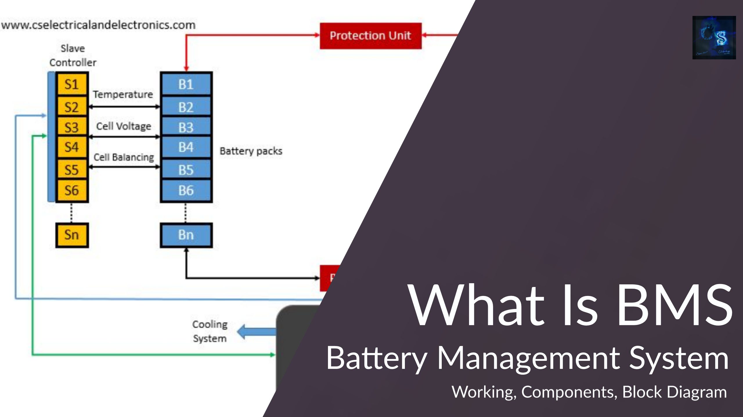
The BMS has some main blocks such as,
- Charger
- Battery pack
- Master unit
- Slave unit
- Protection unit
- Load
- Cooling system
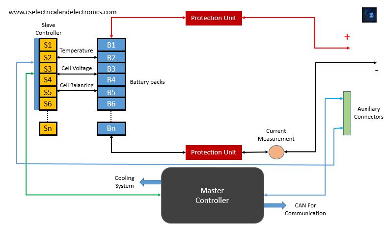
The above image gives you an overview of the battery management system.
01. Master Controller:
It’s the brain of BMS. The function of the master controller is to control 23 slaves, achieve current and charge measurement for the battery pack, achieve temperature measurement of the battery pack, use the voltage measurements from slaves with temperature and current measurements to provide fuel gauge functionality. This also controls the discharge mechanism and supplies control signals to the charging circuit based on SoC (state of charge) measurement.
A master controller controls power to slaves, controls charging, discharging, heating, and cooling of the battery pack. The master controller serves SoC (state of charge) measurement, SoH (state of health) maintenance, and saves calibration data. Master controller derives power from the 12V vehicle battery as well as the battery pack being monitored. This permits cell balancing actually when the vehicle is parked. The master controller communicates to vehicles using CAN protocol.
02. Slave Controllers:
Each battery pack has one slave controller. Slave controller monitor 12 cells in series for temperature, voltage, perform cell balancing and perform diagnostics for each cell. The slave controller will conduct passive or active cell balancing for 12 cells of lithium-ion. Each battery chip can handle 6 to 16 cells (70-V max) for Li-ion battery applications.
The Slave controllers monitor each cell for voltage and temperature and send the digitized data to the master controller via CAN protocol. LCU also conducts active cell balancing. Slave controller derives power from the cells being monitored. Slave controllers acquire a power enable signal from the master controller. Multiple slave controllers will be connected to the master controller based on the voltage needed from the battery pack.
03. Charger:
Charger provides a constant current constant voltage charging circuit. The charging circuit charges the battery based on control signals from the master controller. The source to be charger is supposed to be a high voltage source, which can be the regenerative braking, alternator, or the ac mains.
04. Battery Pack:
The battery pack consists of all the cells connected in parallel and series combinations. The battery pack voltage is supposed to be in the range of 100V to 350V. Each battery pack may have 12 cells in series.
05. Protection Unit:
The protection unit consists of the main relay, pre-charge relay, & fuse to protect the battery pack from overcurrent, overvoltage, under-voltage conditions. The relay driver circuit will be used to control the main relay and pre-charge relay. When any unwanted condition occurs the relay will sense and isolate the battery pack from the load.
06. Load:
The load for the battery pack will be the vehicle motor.
07. Cooling System:
This will maintain the surrounding temperature of the battery pack. The signal to the cooling system will be sent by the master controller.
This was about BMS or Battery management systems. We can conclude that the BMS is used for cell balancing, monitoring voltage, SoC, SoH, current, the temperature of the battery pack, and protecting it under abnormal conditions.
I hope this article ” What Is BMS, Battery Management System ” may help you all a lot. Thank you for reading.
Also, read:
- 10 Free ADAS Projects With Source Code And Documentation – Learn & Build Today
- 10 Tips To Maintain Battery For Long Life, Battery Maintainance
- 10 Tips To Save Electricity Bills, Save Money By Saving Electricity
- 100 (AI) Artificial Intelligence Applications In The Automotive Industry
- 100 + Electrical Engineering Projects For Students, Engineers
- 100+ Indian Startups & What They Are Building
- 1000+ Automotive Interview Questions With Answers
- 1000+ Electronics Projects For Engineers, Diploma, MTech Students