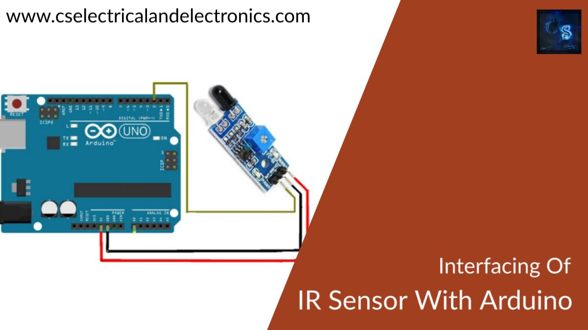
Interfacing Of IR Sensor With Arduino, Code
Hello guys, welcome back to my blog. In this article, I will discuss the interfacing of IR sensor with the Arduino board, code for IR sensor with Arduino board, circuit connections of IR sensor.
If you have any doubts related to electrical, electronics, and computer science, then ask questions. You can also catch me on Instagram – CS Electrical & Electronics And Chetan Shidling.
Also, read:
- Top Best MTech Branches For Electronics & Communication Engineers
- What Is A DC Microgrid, Need & Types Of Controlling Strategies
- Top 15 Food Automation Companies In The World, Food Companies
Interfacing Of IR Sensor With Arduino
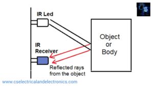
IR stands for Infra-Red. This sensor is an electronic device and senses the presence of obstacles, the motion of the object. It sends the infrared rays through the emitter and receives the reflected rays. In case there is no obstacle the rays are not reflected and the sensor gives a certain output. One feature of this sensor is that these infrared rays are absorbed by black-colored objects and the sensor senses the black color.
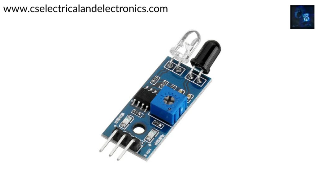
- 01. It holds 3 pins – VCC, Ground, Signal
- 02. In the IR sensor, the signal pin is connected to the digital pin in the development boards like ARDUINO.
- 03. IR sensor provides the output of the digital signal only.
- 04. Operating Voltage of this sensor is +5V.
- 05. This sensor can detect black light.
- 06. The frequency of the IR waves emitted out is about 700nm -1400nm.
- 07. This Infrared Red sensor works on the principles – Plank’s Radiation Law and Wien’s Displacement Law.
Working Of IR Sensor
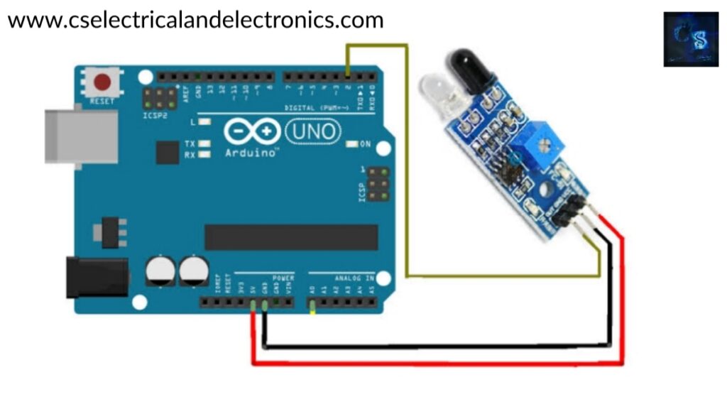
IR Sensor With Arduino
The Sensor connection to the ARDUINO is explained in the following steps: There will be 3 pins present on the IR sensor.
- 01. First pin VCC must be connected to the 5V supply on the ARDUINO board.
- 02. Next, the GROUND pin of the IR sensor must be connected to the ground on the ARDUINO board.
- 03. Finally, the SIGNAL pin of the IR sensor must be connected to any of the digital signal pins on the ARDUINO board.
- 04. The connections from the IR sensor to the ARDUINO board must be connected with the help of a male-female wire.
- 05. Then the power supply is given to the ARDUINO for the functioning of ARDUINO and IR sensor connected to it.
With this entire interfacing of the IR sensor with ARDUINO is successfully completed and the final step is to dump the program to the ARDUINO board for the functioning of the IR sensor and to achieve the output results from the sensor. The functioning of this IR sensor starts when the power supply is given to it. But it is programmed accordingly to expect the results from it as per our necessity.
Arduino Program For IR Sensor
void setup() {
pinMode(2,INPUT);
Serial.begin(9600);
pinMode(13,OUTPUT);
}
void loop() {
Serial.print("IRSensorip  ");
Serial.println(digitalRead(2));
#CS Electrical And Electronics
if(digitalRead(2)==0)
{

digitalWrite(13,HIGH);
}
else{
digitalWrite(13,LOW);
}
}
Function Of IR Sensor
After the successful writing of code in the ARDUINO IDE and successful dumping of the program into the ARDUINO Development Board, the output values of the IR Sensor will be visible on the Serial Monitor. But here the display on the serial monitor is different from the Ultra Sonic sensor serial monitor display. For the IR sensor, since it is a digital output, only the values of 1 and 0 are displayed on the serial monitor.
Explanation Of The Program
Here, the SIGNAL pin of the IR sensor is connected to the digital pin number 2 of the ARDUINO Board. Now, when this program is dumped, there establishes a serial communication between IR Sensor and ARDUINO.
- 01. In the initial step SIGNAL Pin, 2 is selected as INPUT Pin.
- 02. Now serial communication is declared with baud rate 9600.
- 03. Next, Pin 13 is declared as an output pin.
- 04. Now, IR SENSOR is declared in the loop.
- 05. And the read of value from Pin 2 is declared.
- 06. If the read of value from Pin 2 is 0, Output Pin 13 is kept HIGH, or else LOW.
- 07. IR Sensor mainly has an Infrared Receiver, Infrared Source, Medium for the propagation of IR waves.
Here, in this interfacing, if the input read value from the IR sensor is 0, that practically means some object is present in front of the sensor. In that case pin, 13 is kept HIGH. If it reads a value of 1, that practically means no object is present or the black absorbing surface is present. In that case Pin, 13 is kept LOW.
Conclusion
The above-given data is all about the interfacing of the IR sensor with ARDUINO and it is working and the output results of the IR sensor. This information can be used to understand briefly about the IR sensor working with ARDUINO and promote the development of Autonomous Robotic Projects by using the IR sensor and other components as well.
I hope this article may help you all a lot. Thank you for reading.
Also, read:
- 100 + Electrical Engineering Projects For Students, Engineers
- 1000+ Electronics Projects For Engineers, Diploma, MTech Students
- 1000+ MATLAB Simulink Projects For MTech, Engineering Students
- 500+ Embedded System Projects For Engineer, Diploma, MTech, PhD
- 500+ Projects For Diploma Electrical, Electronics Student, Diploma Project
- 8051 Microcontroller Timers, TCON Register, TMOD Register
- Advancements In 3D Printing Technology And It’s Future
- Advancements In Power Electronics For Energy Efficiency
Author Profile
- Chetu
- Interest's ~ Engineering | Entrepreneurship | Politics | History | Travelling | Content Writing | Technology | Cooking
Latest entries
 All PostsApril 19, 2024What Is Vector CANoe Tool, Why It Is Used In The Automotive Industry
- All PostsApril 13, 2024What Is TCM, Transmission Control Module, Working, Purpose,
- All PostsApril 12, 2024Top 100 HiL hardware in loop Interview Questions With Answers For Engineers
- All PostsMarch 22, 2024Driver Monitoring Systems In Vehicles, Working, Driver Sleepy Alert