Different Types Of Filters Used In Electronics And Electrical Devices
Hello guys, welcome back to our blog. In this article, we will discuss the different types of filters used in electronics and electrical devices, low pass filters, high pass filters, band pass filters, band-reject filters, comparison between filters, advantages and disadvantages of filters, and applications of filters.
If you have any electrical, electronics, and computer science doubts, then ask questions. You can also catch me on Instagram – CS Electrical & Electronics.
Also, read:
- Top 17 CAN Protocol Questions Asked In An Interview With Answers
- Data Structures Coding Questions Asked In Online Test In 2022
- Top 50+ Interview Questions And Answers On VLSI CMOS Circuits
Types Of Filters
In earlier days we didn’t have any filter that reduces a ripple in the output. So, the design of a filter is introduced to remove the ripples in the output. The designing of a filter is having requirements and the filter must fulfill all those requirements to get a satisfying output. To fulfill those requirements the filter is designed.
A filter is a device that is used to remove unwanted elements in the output. The process of eliminating unwanted features in the output is called filtering. By using these filters we get the desired output without ripples. Whenever we use a filter the output is free from ripples it gives good results in the output and it improves the working capability of the device. Nowadays there are a lot of applications are having a filter because from every device we expect an error-free output and that was done by using a filter.
Different Types Of Filters
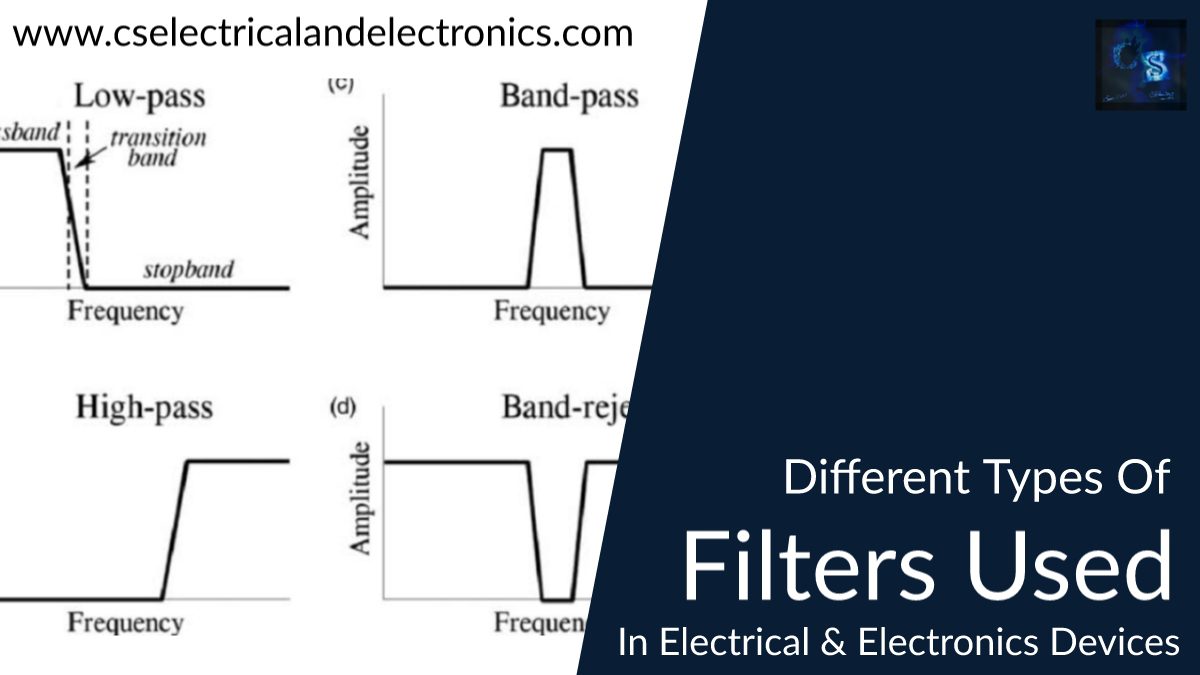
01. Low pass filter
A low pass filter is a filter that passes signals which is of lower frequency signals than a certain selected cutoff frequency and rejects the frequency signals which are higher than the selected cutoff frequency. Low pass filters are designed by using resistors with a combination of inductors or capacitors. A resistor forms a circuit with an inductor then it is an RL low pass filter or a resistor forms a circuit with a capacitor then it is called RC low pass filter.
Circuit Diagram Of Low Pass RL Filter
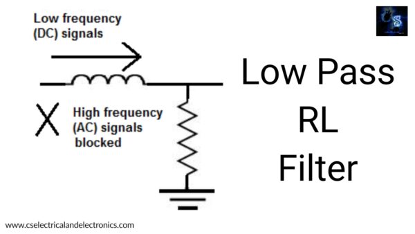
Working Of Low Pass RL Filter
The low pass RL filter working is based on inductive reactance. Within the inductive reactance, the resistance or impedance and inductance are changed depending on the frequency of the signal passing through the inductor. The frequency and the inductive reactance are directly proportional so whenever the frequency will be zero( in DC) the reactance is also reduced similarly if the frequency increases (in AC) the inductive reactance also increases. To the above information, a low-pass RL filter works effectively. It allows low-frequency signals and blocks high-frequency signals by connecting the inductor in series with the supply.
Circuit Diagram Of Low Pass RC Filter
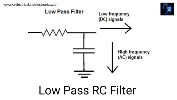
Working Of Low Pass RC Filter
The low-pass RC filter works based on the principle of capacitive reactance. The capacitive reactance and frequency are inversely proportional, so whenever the frequency increases(in AC) the reactance gone be decreased, if the frequency is zero(in DC) then the reactance increases. By this, we say that a low-pass RC filter allows low-frequency signals and blocks high-frequency signals by connecting capacitors across the supply. If high-frequency signals pass in the capacitor then it went be grounded, finally, it only allows low signal frequency.
In the above two cases, the low pass filter allows low-frequency signals and blocks high-frequency signals effectively.
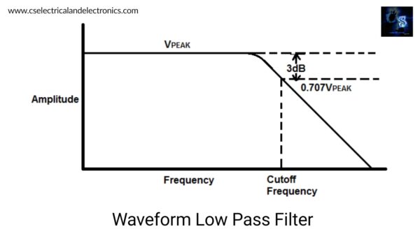
Frequency response
02. High Pass Filter
The high pass filter is a filter that is used to pass signals with a frequency higher than the selected certain cut-off frequency and rejects the signals with a frequency lower than the cut-off frequency. The amount of rejection frequency depends on the design of the filter.
High pass filters are designed by using resistors with the combination of inductor and capacitor. If a resistor forms a circuit with the combination of inductors then it is a high pass RL filter or if a resistor forms a circuit with the combination of the capacitor then it is a high pass RC.
Circuit Diagram Of High Pass RL Filter
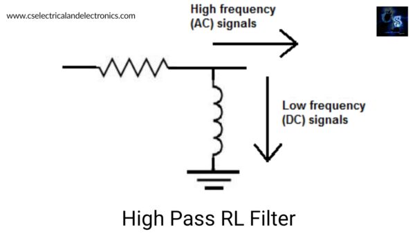
Working Of High Pass RL Filter
In the RL filter, the inductor is also a reactive element as same as a capacitor but the difference is the inductive reactance is directly proportional to the frequency. Based on the frequency, the resistance went be varied. If the frequency increases (in AC) then reactance gone be increasing similarly to frequency zero (in DC) then reactance will be zero. In the inductor absolutely some low signal frequency passes but that low signal frequency is grounded so, finally, it allows high-frequency signals and rejects low signal frequency by connecting the inductor in parallel with the Power supply.
Circuit Diagram Of High Pass RC Filter
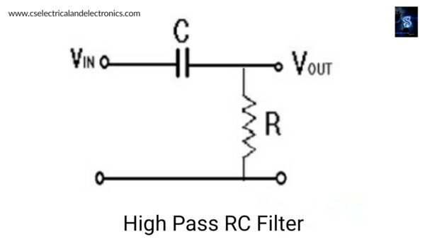
Working Of High Pass RC Filter
In the RC filter, the capacitor is a reactive element, which gives a difference in resistance based on the signals of different frequencies that entered the capacitor. A capacitor reactance is inversely proportional to the frequency so, if the frequency increases(in AC) then the reactance will be decreasing, or if the frequency tends to zero(in DC) then the reactance will be increasing.
So, from this, we can say that the low-pass RC filter allows the high signal frequency and rejects the low signal frequency by connecting the capacitor in series with the supply.
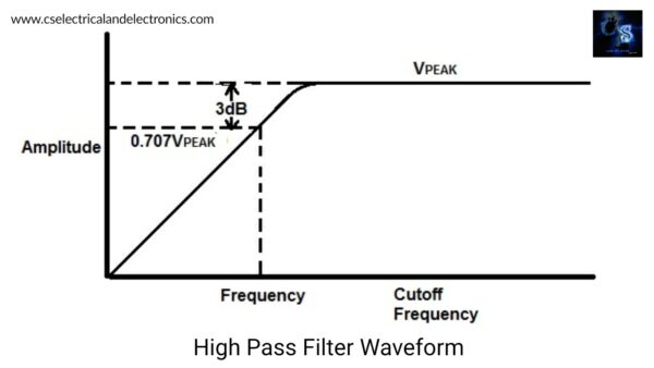
From the above, we finally say that whatever the circuit but the high pass filter allows high-frequency signals and rejects low-frequency signals.
Frequency response:
03. Band Pass Filter
A bandpass filter is a filter that passes frequency signals within a certain value of band frequency and rejects frequency signals outside that particular band range. A bandpass filter is a combination of a low-pass filter and a high-pass filter. The bandpass filter is designed by cascading the low pass filter and high pass filter.
Whenever we cascade those two filters it will introduce an overlapping situation so, the place where both filters overlap is called the Bandpass from this information we form a circuit for a bandpass filter.
Circuit Diagram Of band Pass Filter
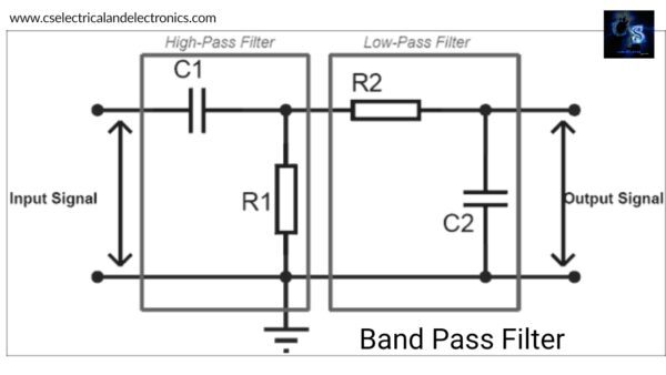
Working Of Band Pass Filter
The Bandpass filter is the combination of a low pass filter and a high pass filter so, the low pass filter passes low-frequency signals and the high pass filter passes high-frequency signals but the Bandpass filter passes the signals within a certain range of the frequency band. In a bandpass filter having two cut-off frequencies from this, we say that the difference between those two cut-off frequencies will give a Bandwidth value of the filter.
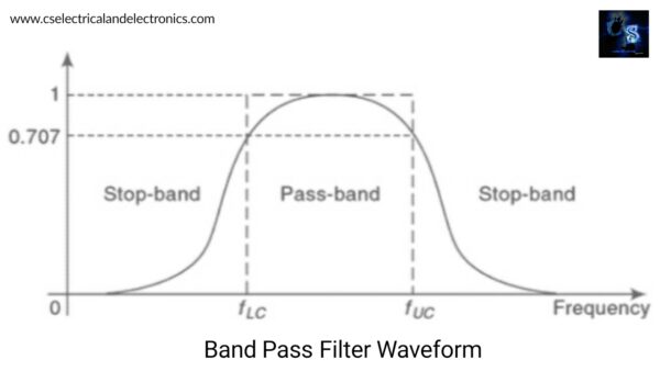
That two cut-off frequency is formed by a low pass filter and high pass filter so, one of the frequency is the lower cutoff frequency and another one is the cut-off frequency. If the lower cut-off frequency is higher than that of the higher cut-off frequency then the bandpass filter works correctly.
Frequency response:
04. Band Reject Filter
A band rejects filter is also called a band-stop filter or notch filter. So, this filter rejects a certain band of frequencies and it passes all other frequencies which are out of this particular band. The bandstop filter is designed by combining a low-pass filter and a high-pass filter. The bandstop filter compliment the bandpass filter.
Circuit Diagram Of Band Reject Filter
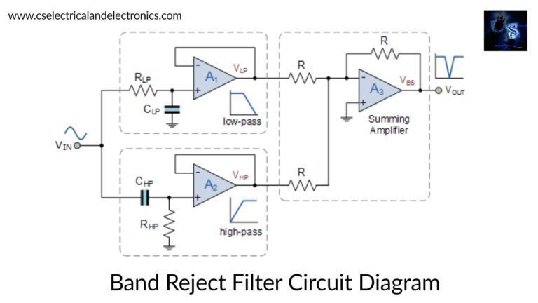
Working Of Band Reject Filter
The bandstop filter is the combination of a low pass filter and high pass filter and that summing amplifier is used to improve the strength of the signal. Whenever low signal frequency passes then the low pass filter will work and similarly, the high pass filter also works whenever the high signal frequency passes. but here the operation of the bandstop filter is to reject the outsides band frequency signal that can be obtained by using this circuit because it gives phase opposition in reverse to the bandpass filter.
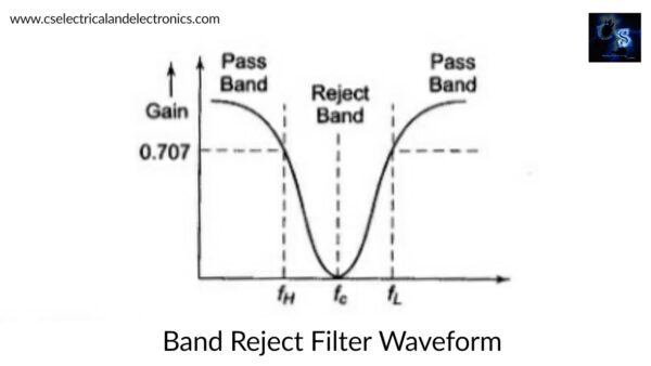
Frequency response:
Difference between low pass, high pass, band pass, and band reject filters or types of filters
| Parameters | Low pass filter | High pass filter | Bandpass filter | Band reject filter |
| Frequency | Lower than 70.7% | Higher than 70.7% | 300MHz to100GHz | 200Hz to 500Hz |
| Operation | Allows low-frequency signals | Allows high-frequency signals | Allows the frequency signals within the band | Allows some frequency signals from out of the band |
| Cost | very low | Moderate | High | High |
| Applications | Musical systems | Photoshop | Wireless transmitters and receivers | Speakers |
Advantages of types of filters:
- Filters remove the unwanted elements due to this the performance of the device is improved
- By using a filter we get the desired output
- They are economical
- It consumes less power to do a work
- It requires only passive elements so, by using this it is easy to design
- The efficiency of the device increases because there are no errors or ripples in the output
- Easy to operate
Disadvantages of types of filters
- Limited Bandwidth
- It doesn’t use for bulky operations
- Increased sensitivity to variation in circuit parameters
Applications of types of filters
There are a lot of applications are having filters. Those filters are different types used for different applications those are:
01. Low pass filters are mainly used in electronic circuits such as a hiss filter used in audio, Anti-aliasing filters for conditioning signals prior to analog to digital conversion, digital filters for smoothing sets of data, acoustic barriers, blurring of images, etc.
02. High pass filters are used in audio speakers to reduce the high-frequency noise produced in the system and it is also used in equalizers to avoid low-frequency signals.
03. Bandpass filters are mainly used in wireless transmitters and receivers and radio Transmitters are used to block the harmonic emissions. The main function of a filter in a transmitter is to limit the bandwidth of the output signal to the band allocated for the transmission.
04. Band reject filters are mainly used in public address systems and speaker systems for ensuring good quality of audio. This filter is also used in crucial telephone technology, by using these filters we can reduce the line noise of signal transmission.
This was about “Types Of Filters“. I hope this article may help you all a lot. Thank you for reading.
Also, read:
- 100 + Electrical Engineering Projects For Students, Engineers
- 1000+ Electronics Projects For Engineers, Diploma, MTech Students
- 1000+ MATLAB Simulink Projects For MTech, Engineering Students
- 500+ Embedded System Projects For Engineer, Diploma, MTech, PhD
- 500+ Projects For Diploma Electrical, Electronics Student, Diploma Project
- 8051 Microcontroller Timers, TCON Register, TMOD Register
- Advancements In 3D Printing Technology And It’s Future
- Advancements In Power Electronics For Energy Efficiency
Author Profile
Latest entries
 All PostsJanuary 21, 2021Different Types of Tesla Electric Cars, Tesla Cars Models
- All PostsNovember 2, 2020Difference Between Earthing and Grounding, Definition
- All PostsSeptember 27, 2020Differences Between Electric Cars and Diesel cars, History
- All PostsSeptember 27, 2020Difference Between Diode and SCR (Silicon Controlled Rectifier)