Differences Between The Clipper Circuit And Clamper Circuit
Hello guys, welcome back to my blog. In this article, I will discuss the difference between the clipper circuit and clamper circuit, what is the clipper circuit, and what is the clamper circuit.
If you have any electrical, electronics, and computer science doubts, then ask questions. You can also catch me on Instagram – CS Electrical & Electronics.
Also. read:
- Top 20 AUTOSAR Interview Questions For AUTOSAR Engineers
- Products Manufactured By Texas Instruments In Various Domains
- Top 12 Microcontroller Manufacturing Companies In The World
Clipper Circuit And Clamper Circuit
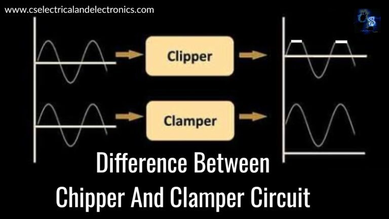
Clippers and clampers both play an important role in various electronic applications. We can find major applications of both circuits in analog electronics. Clipper and clamper are made with diodes but opposite each other in almost all aspects like working, construction and application, etc. If we want to clip a portion of the waveform, we have to use the clipper. Suppose if we want to shift the DC voltage level upward or downward, we have to use clamper circuits. In this article let’s study some fundamental differences between them.
What is a clipper circuit?
The circuit limits the amplitude of the given input signal by clipping a particular part of the input signal without affecting the remaining part of the signal. The clipping method can be used where excessive voltage must not pass through the components. If this voltage passes through some components, it may get demolished. To avoid this, a particular value is obtained by clipping the amplitude of the signal by using a clipper circuit.
Example: Halfwave rectifier. This circuit contains a resistor, a diode, and an AC source.
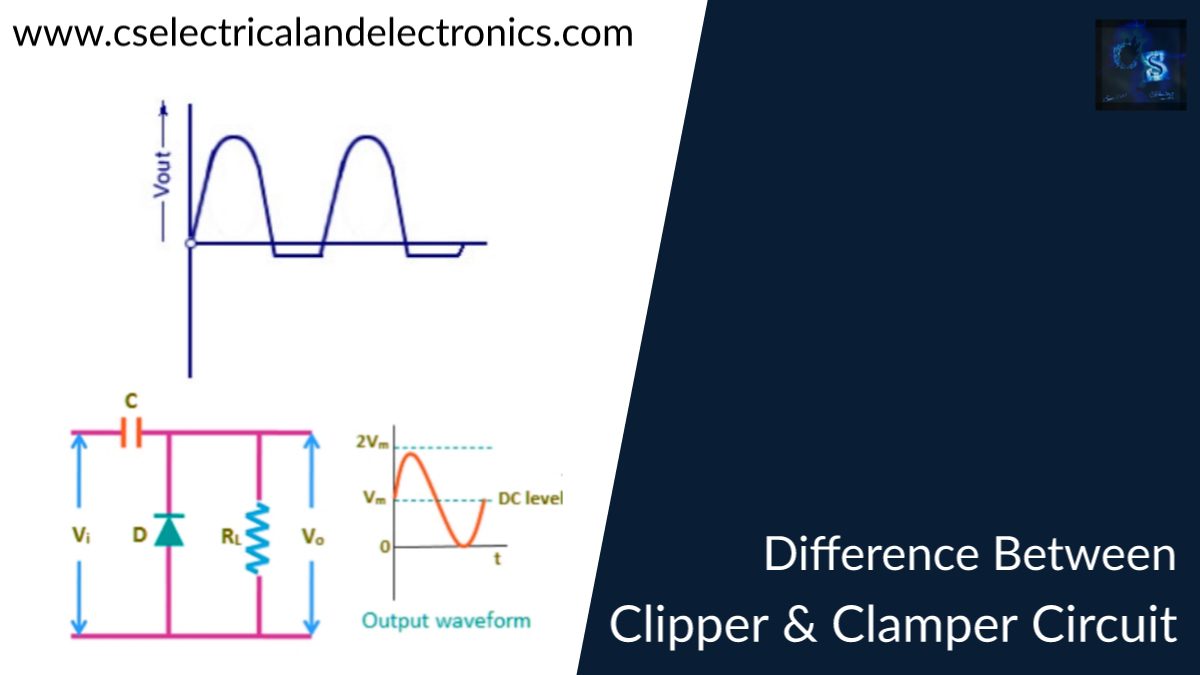
What is a clamper circuit?
The circuit which does not clip/reduce the input signal, instead it shifts the level of DC input voltage either upward or downward, depending upon the positive clamper circuit or negative clamper circuit is known as a clamper circuit. In the clamper circuit, a capacitor is used as an energy storage component. It contains a diode, a resistor, a capacitor, and an input AC source.
Differences between circuits
01. Clipper is a limiting circuit that limits the output voltage, whereas the clamper circuit shifts the DC level of the voltage output.
02. Regarding the shape of the output waveform in the Clipper circuit, the voltage clipped by a Clipper assumes various forms, whereas in the clamping the output voltage waveform does not alter in shape.
03. The output voltage is less than the input voltage in Clipper circuits, whereas, in the clamper circuits, the output voltage is multiple of the input.
04. DC level remains unchanged in the Clipper circuit, whereas the DC level gets shifted in the clamper circuit.
05. Energy storage component is not needed in the Clipp circuit whereas the clamper circuit capacitor is used as an energy storage component.
06. Clipper circuit is a current delimiter, voltage delimiter, or amplitude delimiter, whereas a clamper circuit, can be called a voltage multiplier circuit, and in removing distortions in TV.
07. Clipper circuit can be used in the transmitter, amplitude selector, receiver, and noise limiter whereas the clamper circuit can be used in sonar, radar system, and voltage multiplying circuit.
08. In the clipper circuit, the shape of the output waveform changes to sinusoidal rectangular or triangular et cetera whereas in the clamper circuit the shape of the output waveform remains similar to the input waveform, i.e. the output waveform is always sinusoid.
This was about “Clipper Circuit And Clamper Circuit“. I hope this article may help you all a lot. Thank you for reading.
Also, read:
- 100 + Electrical Engineering Projects For Students, Engineers
- 1000+ Electronics Projects For Engineers, Diploma, MTech Students
- 1000+ MATLAB Simulink Projects For MTech, Engineering Students
- 500+ Embedded System Projects For Engineer, Diploma, MTech, PhD
- 500+ Projects For Diploma Electrical, Electronics Student, Diploma Project
- 8051 Microcontroller Timers, TCON Register, TMOD Register
- Advancements In 3D Printing Technology And It’s Future
- Advancements In Power Electronics For Energy Efficiency
Author Profile
-
Ships annigeri
Department of Electrical and Electronics engineering, B.L.D.E.A's V.P.Dr.P.G.Halalatti college of engineering and technology Vijayapur.
Latest entries
 All PostsOctober 17, 2021Mphasis Hiring Process, Online Test, Mphasis Interview Questions
- All PostsOctober 17, 2021Top 10+ Features Of Java Programming Language You Must Know
- All PostsOctober 13, 2021Difference Between Java And Cpp Programming Languages, Applications
- All PostsOctober 10, 2021What is JAVA, Applications of JAVA, History, Code On Java