Hello guys, welcome back to m blog. In this article, I will discuss the block diagram of the battery management system (BMS) with some short detail on the battery management system.
If you have any electrical, electronics, and computer science doubts, then ask questions. You can also catch me on Instagram – CS Electrical & Electronics
Also, read:
- Top 14 Types Of Relay In Power Systems, Working, Purpose
- Top 100+ MATLAB Simulink Projects With SLX File For Engineers
- What Is Kalman Filter, Types, Applications, Algorithms For Kalman Filters
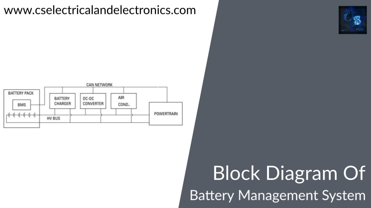
Block Diagram Of Battery Management System
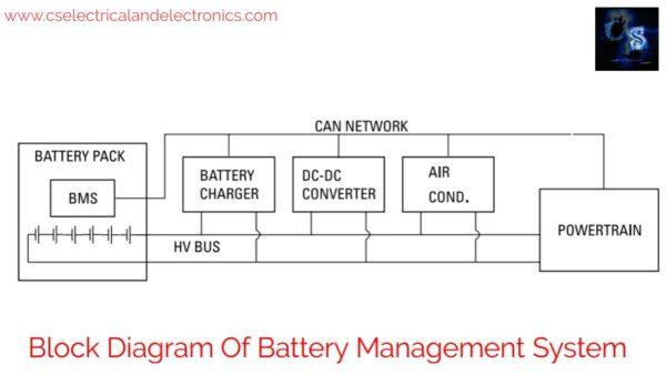
The approach of lithium-ion batteries has brought a significant shift in the area of the large-format battery system. Earlier limited to heavy and bulky lead-acid storage batteries, large-format batteries were used only where absolutely necessary as a means of energy storage. The above block diagram consists of the battery pack, battery charger, dc-dc converter, air conditioner, etc.
BMS or Battery Management System plays a very important role in electric vehicles. To monitor and maintain the battery pack for proper usage, a BMS is needed. BMS contains master and slave controllers. The battery pack is nothing but the number of cells connected in series and parallel combinations.
Master is the brain of BMS. The function of the master controller is to control 23 slaves, achieve current and charge measurement for the battery pack, achieve temperature measurement of the battery pack, and use the voltage measurements from slaves with temperature and current measurements to provide fuel gauge functionality. This also controls the discharge mechanism and supplies control signals to the charging circuit based on SoC (state of charge) measurement.
A master controller controls power to slaves and controls charging, discharging heating, and cooling of the battery pack. The master controller serves SoC (state of charge) measurement, and SoH (state of health) maintenance, and saves calibration data. The master controller derives power from the 12V vehicle battery as well as the battery pack being monitored. This permits cell balancing actually when the vehicle is parked. The master controller communicates to vehicles using CAN protocol.
Each battery pack has one slave controller. The slave controller monitor 12 cells in series for temperature, and voltage, performs cell balancing, and perform diagnostics for each cell. The slave controller will conduct passive or active cell balancing for 12 cells of lithium-ion. Each battery chip can handle 6 to 16 cells (70-V max) for Li-ion battery applications.
The Slave controllers monitor each cell for voltage and temperature and send the digitized data to the master controller via CAN protocol. LCU (also known as slave) also conducts active cell balancing. The slave controller derives power from the cells being monitored. Slave controllers acquire a power enable signal from the master controller. Multiple slave controllers will be connected to the master controller based on the voltage needed from the battery pack.
The main functions of BMS are
- Cell balancing: equalizing the Soc and voltage of each cell
- Protecting the battery pack from overcurrent, overvoltage, & under-voltage conditions
- Monitoring the temperature, & isolating the BMS if the temperature exceeds
- Monitoring current, voltage, SoC (state of charge), SoH (state of health)
- Efficient charging & discharging
The battery management system is used for lithium-ion batteries in EVs to manage the battery pack for things such as overcharge, over-discharge, balance charging, and fault.
A battery management system (BMS) is an electronic system that manages a rechargeable battery such as by protecting the battery from operating outside its safe operating area, monitoring its state, calculating secondary data, reporting that data, and controlling its environment.
A BMS monitors the state of the battery such as:
01. Voltage – Total voltage, voltages of individual cells, minimum and maximum cell voltage, or voltage of periodic taps.
02. Temperature – Average temperature, coolant intake temperature, coolant output temperature, or temperature of individual cells.
03. State of charge – Indicate the charge level of the battery.
04. State of health – Shows the remaining capacity of the battery as % of the original capacity.
05. State of safety – the battery is operating under safe mode or not.
06. State of power – it will estimate the power of the pack.
07. CAN – The CAN network is used to make communication between battery charger, dc-dc converter, air conditioner, etc.
I hope this article may help you all a lot. Thank you for reading.
Also, read:
- 10 Tips To Maintain Battery For Long Life, Battery Maintainance
- 10 Tips To Save Electricity Bills, Save Money By Saving Electricity
- 100 (AI) Artificial Intelligence Applications In The Automotive Industry
- 100 + Electrical Engineering Projects For Students, Engineers
- 100+ Indian Startups & What They Are Building
- 1000+ Automotive Interview Questions With Answers
- 1000+ MATLAB Simulink Projects For MTech, Engineering Students
- 2024 Is About To End, Let’s Recall Electric Vehicles Launched In 2024


Does this system have a sample simulink model?