BLDC Motor Control Methods, Best Controlling Method, Benefits
Hello guys, welcome back to our blog. Here in this article, we will discuss BLDC motor control methods, the best controlling method for BLDC motor, with advantages and disadvantages,
If you have any electrical, electronics, and computer science doubts, then ask questions. You can also catch me on Instagram – CS Electrical & Electronics.
Also, read:
- Top 100 Electrical Companies In The World Where You Can Work
- What Is Unified Power Flow Controller (UPFC), Purpose, Applications
- Top 10 Electric Scooters In India, Best EV Scooties In 2022
BLDC Motor Control Methods
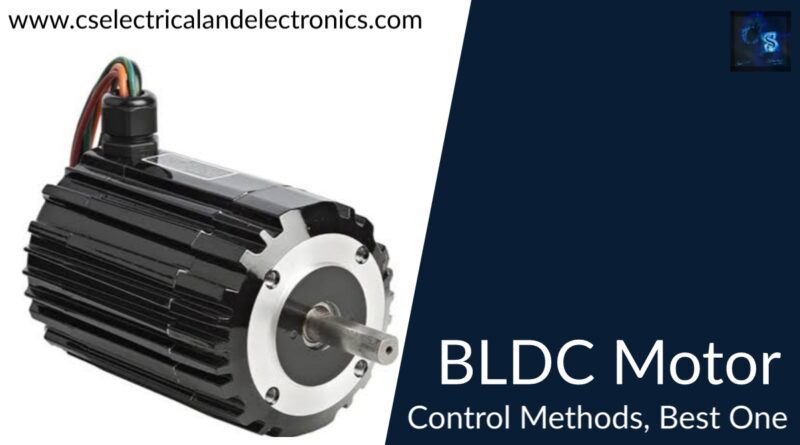
BLDC stands for “ Brushless Dc motor”. That means these motors do not have brushes in them.
Brushless DC electric motors can also be called electronically commutated motors, which are powered by DC electric source through an integrated inverter or switching power supply, which produces an AC electric signal to drive the motor.
The stator has 3 phase winding, while the rotor is in the form of a permanent magnet.

The rotating of the rotor will completely depend on the current produced by the stator, and the speed can be controlled by controlling the stator current.
BLDC motor consists of rotor position sensors that produce electric signals. These electric signals indicate the current position of the rotor.
The stator winding of the BLDC motor can be driven from an electronic drive, which will be 3 phase inverter.
The speed of the BLDC motor can be controlled by controlling the voltage of the stator, which can be achieved by controlling the inverter DC input voltage.
Top BLDC Motor Control Methods
Brushless DC motor (BLDC) substitutes the mechanical commutator with an electronic commutator, simply because of the electronic commutator, the BLDC motor requires a controller to drive the circuit.
Presently, there are three control strategies for BLDC motor: FOC (called field-oriented control, vector frequency control, magnetic-field vector directional control), square-wave control (also understood as trapezoidal wave control, 6-step commutation control, 120° control ), and sine wave control.
01. FOC (Field Oriented Control) control
Sine wave control recognizes the control of the voltage vector and indirectly acknowledges the current control, but it can not manipulate the direction of the current. FOC control can be considered as a glorified sine wave control, it recognizes the control of the current vector, i.e. discovering the vector control of the motor’s stator magnetic field.
As field-oriented control manipulates the direction of the motor’s stator magnetic field, it can control the motor’s stator magnetic field and the rotor magnetic field at 90° all the period, thus reaching a maximum torque output under a particular current.
The advantages of field-oriented control contain small torque ripple, high efficiency, lower noise, and quick dynamic response.
Disadvantages possess increased hardware cost, increased requirements for controller performance, and motor parameters that must be matched.
02. Square-wave control
Square-wave control utilizes a Hall sensor or sensorless computation algorithm to get the position of the motor rotor, and then commutates six times in the 360° electrical rotation according to the position of the rotor (commutate per 60°).
The motor outputs a precise direction force at an individual commutation position, so it can be stated that the positional precision of the square-wave control is electrical 60°. In this control process, the phase current waveform of the motor comes from the square wave, so it is called square-wave control.
The advantage of square-wave control contains a straightforward control algorithm, lower hardware cost, and more increased motor speed that can be acquired by utilizing an ordinary controller.
The disadvantage of square-wave control contains: an extensive torque ripple, a specific current noise, and efficiency is not up to the maximum. Square-wave control is appropriate for occasions where motor rotation arrangement is not very high.
03. Sine wave control
Sine wave control utilizes the SVPWM (space vector pulse width modulation) wave and outputs the three-phase sine-wave voltage, the related current is sinusoidal current. In such a control method, there’s no idea of commutation as the square-wave control, nor it assumes that infinite commutations have appeared in an electric cycle.
Apparently, sine wave control has less torque ripple and smaller current harmonics than the square-wave control, its command is more “outstanding”. Nevertheless, it has more increased performance requirements for the controller than the square-wave control, the motor efficiency can not be the highest.
Due to its specific advantages, FOC control has slowly superseded the standard control mode in many applications and succeeded in significant favor in the motion control field.
This was about “BLDC Motor Control Methods“. I hope this article may help you all a lot. Thank you for reading.
Also, read:
- 10 Tips To Maintain Battery For Long Life, Battery Maintainance
- 10 Tips To Save Electricity Bills, Save Money By Saving Electricity
- 100 (AI) Artificial Intelligence Applications In The Automotive Industry
- 100 + Electrical Engineering Projects For Students, Engineers
- 1000+ Control System Quiz, Top MCQ On Control System
- 1000+ Electrical Machines Quiz, Top MCQs On Electrical Machines
- 1000+ MATLAB Simulink Projects For MTech, Engineering Students
- 50 Tips To Save Electricity At Home, Shop, Industry, Office
Author Profile
- Chetu
- Interest's ~ Engineering | Entrepreneurship | Politics | History | Travelling | Content Writing | Technology | Cooking
Latest entries
 All PostsApril 29, 2024Top 11 Free Courses On Battery For Engineers With Documents
 All PostsApril 19, 2024What Is Vector CANoe Tool, Why It Is Used In The Automotive Industry
 All PostsApril 13, 2024What Is TCM, Transmission Control Module, Working, Purpose,
 All PostsApril 12, 2024Top 100 HiL hardware in loop Interview Questions With Answers For Engineers


